
Fiber Channel (FC) explained & Basic configuration

Contents
What is Fiber Channel:
Fibre Channel (FC) is a high-speed data transfer protocol providing in-order, lossless delivery of raw block data. Fibre Channel is primarily used to connect computer data storage to servers in storage area networks (SAN) in commercial data centers.
The maximum total frame length is 2148 bytes.

II- Fiber Channel port types:
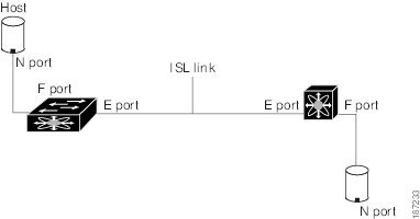
E Port:
E port: In expansion port (E port) mode, an interface functions as a fabric expansion port. This port may be connected to another E port to create an Inter-Switch Link (ISL) between two switches. E ports carry frames between switches for configuration and fabric management.
F Port:
In fabric port (F port) mode, an interface functions as a fabric port. This port may be connected to a peripheral device (host or disk) operating as an N port. An F port can be attached to only one N port.
NP Port:
When the switch is operating in NPV mode, the interfaces that connect the switch to the core network switch are configured as NP ports. NP ports operate like N ports that function as proxies for multiple physical N ports.
TE Port
In trunking E port (TE port) mode, an interface functions as a trunking expansion port. It may be connected to another TE port to create an extended ISL (EISL) between two switches.
SD Port
In SPAN destination port (SD port) mode, an interface functions as a switched port analyzer (SPAN). The SPAN feature monitors network traffic that passes through a Fibre Channel interface. This monitoring is done using a standard Fibre Channel analyzer (or a similar switch probe) that is attached to an SD port. SD ports do not receive frames, instead they transmit a copy of the source traffic.
Auto Mode
Interfaces configured in auto mode can operate in one of the following modes: F port, E port, or TE port. The port mode is determined during interface initialization. For example, if the interface is connected to a node (host or disk), it operates in F port mode. If the interface is attached to a third-party switch, it operates in E port mode. If the interface is attached to another switch in the Cisco Nexus 5000 Series or Cisco MDS 9000 Family, it may become operational in TE port mode.
III- Switch Priority
By default, the configured priority is 128. The valid range to set the priority is between 1 and 254. Priority 1 has the highest priority. Value 255 is accepted from other switches, but cannot be locally configured.
Any new switch can become the principal switch when it joins a stable fabric. During the principal switch selection phase, the switch with the highest priority becomes the principal switch. If two switches have the same configured priority, the switch with the lower WWN becomes the principal switch.
The priority configuration is applied to runtime when the fc domain is restarted. This configuration is applicable to both disruptive and nondisruptive restarts.
Principal switch selection in a fabric is based on the following values:
■ Run-time priority: The lowest run-time priority is considered the highest priority.
By default, the configured priority is 128. The valid range to set the priority is between 1 and 254. The value 255 is accepted from other switches but cannot be locally configured.
■ Switch WWN: The lowest switch WWN is given higher priority.
During the principal switch selection phase, the switch with the highest priority becomes the principal switch. If two switches have the same configured priority, the switch with the lower World Wide Name (WWN) becomes the principal switch.
Domain ID Distribution:
When a subordinate switch requests a domain, the following process takes place:
■ The local switch sends a configured domain ID request to the principal switch.
■ The principal switch assigns the requested domain ID if available. Otherwise, it assigns another available domain ID.
IV- Fiber Channel Basic Configuration:
- Convert Ethernet port to Fiber channel on Nexus switches:
N5K-A(config)# slot 1
N5K-A(config-slot)# port 47-48 type fc
Port type is changed. Please reload the switch
N5K-A(config-slot)# copy running-config startup-config
[########################################] 100%
Copy complete, now saving to disk (please wait)...
N5K-A(config-slot)# reload- Port channel configuration:
N5K-A(config)# interface fc1/47-48
N5K-A(config-if)# channel-group 10
fc1/47 fc1/48 added to port-channel 10 and disabled
please do the same operation on the switch at the other end of the port-channel, then do "no shutdown" at both ends to bring it up.
N5K-A(config-if)# no shutdown
N5K-A(config)# interface san-port-channel 10
N5K-A(config-if)# switchport trunk allowed vsan 11
Warning: This command will remove all VSANs currently being trunked and trunk only the specified VSANs.
Do you want to continue? (y/n) [n] yby default, the port-channel mode is “on”, you can change the port-channel mode to active by adding this command “channel mode active” under “interface san-port-channel X” mode.
- Configure a VSAN and assign a node interface to it:
MDS1# conf t
Enter configuration commands, one per line.  End with CNTL/Z.
MDS1(config)# vsan database

MDS1(config-vsan-db)# vsan 101 name VSAN101
MDS1(config-vsan-db)# vsan 101 interface fc1/15

MDS1(config)# interface fc1/15
MDS1(config-if)# no shut
- Checking Flogi and FCNS databases:
MDS1# show flogi data
MDS1# show fcns database- SAN Trunking:
MDS1(config)# int fc1/8
MDS1(config-if)# switchport mode e
MDS1(config-if)# switchport trunk allowed vsan 101
MDS1(config-if)# no shut
MDS1(config-if)# 2014 Aug 16 00:59:50 MDS1 %PORT-5-IF_TRUNK_UP: %$VSAN 101%$ Interface fc1/1, vsan 101 is up

MDS2(config)# int fc1/8
MDS2(config-if)# switchport mode e
MDS2(config-if)# switchport trunk all vsan 101
MDS2(config-if)# no shut- Zoning:
Fibre Channel zoning allows you to partition the Fibre Channel fabric into one or more zones. Each zone defines the set of Fibre Channel initiators and Fibre Channel targets that can communicate with each other in a VSAN. Zoning also enables you to set up access control between hosts and storage devices or user groups.
The access and data traffic control provided by zoning does the following:
• Enhances SAN network security
• Helps prevent data loss or corruption
• Reduces performance issues
Note Zoning is configured on a per-VSAN basis. You cannot enable zoning at the fabric level.
Each zone set consists of one or more zones. You can use zone sets to enforce access control within the Fibre Channel fabric. In addition, zone sets provide you with the following advantages:
• Only one zone set can be active at any time.
• All zones in a zone set can be activated or deactivated as a single entity across all switches in the fabric.
• A zone can be a member of more than one zone set.
• A switch in a zone can have a maximum of 500 zone sets.
Configuration:
We will create a zone set and configure a zone inside of it and then assign members (hosts and arrays) to the zone:
MDS1(config)# zoneset name VSAN101 vsan 101
MDS1(config-zoneset)# zone name Zone-a
MDS1(config-zoneset-zone)# member pwwn 20:1f:00:27:6b:46:89:00
MDS1(config-zoneset-zone)# member pwwn 21:00:00:b8:3a:1c:79:0a
Then we will activate the zoneset:
zoneset activate name VSAN101 vsan 101Share zoneset to the Fabric:
zoneset distribute full vsan 101Verify active zoneset:
MDS1# show zoneset active
Autozone
The Autozone feature is a mechanism to automate zoning of devices. This feature can be used to reduce the administrative overhead of manually creating and updating the switch zone configuration each time a device is added to the SAN to a one-time command. An administrator has to configure the Autozone feature after the initial deployment and does not have to manually change or modify the zone configuration each time a new device is
added to a fabric. The Autozone feature is intended for fabrics composed of a single fabric switch that has no more than 100 devices connected.
Initially, Autozone configures zoning that enables connectivity from every initiator to every target. The zones that are created are placed in a single zone set in VSAN 1 and activated.
When in automatic mode, a Scheduler job is created to scan for newly logged-in devices every five minutes. New initiators are zoned with all the targets, and new targets are zoned with all the initiators. The new zones are then added to the active zone set. This process allows the switch to be administered with minim al effort by simply plugging in new devices and having automatic connectivity for the devices within minutes.
Zone Merge
All Cisco SAN switches distribute active zone sets when new E port links come up or when
a new zone set is activated in a VSAN. When two switches in a fabric are merged using a TE
or E port, these TE and E ports may become isolated when the active zone set databases are
different between the two switches or fabrics, as shown in Figure 7-29. When a TE port or
an E port becomes isolated, you can recover that port from its isolated state using one of
three options:
■ Import the neighboring switch’s active zone set database and replace the current active
zone set.
■ Export the current database to the neighboring switch.
■ Manually resolve the conflict by editing the full zone set, activating the corrected
zone set, and then bringing up the link.
Fibre Channel Aliasing:
Fibre Channel aliases allow the administrator to assign a plain text, human readable name to a pWWN,
FC ID, interface, IP address, nWWN or symbolic node name. Fibre Channel aliases are restricted to the
VSAN in which they were created. The most common and recommended Fibre Channel alias is the
pWWN, which is the basis for this procedure:
ca-9506(config)# fcalias name host1_fcaw0 vsan 804
ca-9506(config-fcalias)# member pwwn 22:35:00:0c:85:e9:d2:c2
ca-9506(config-fcalias)# exit
- Create the zone using the Fibre Channel aliases:
ca-9506(config)# zoneset name ZS_Engr_primary vsan 804
ca-9506(config-zoneset)# zone name Z_host1_fcaw0_symm78FA03ab
ca-9506(config-zoneset-zone)# member fcalias host1_fcaw0
References:
en.wikipedia.org/wiki/Fibre_Channel
sciencedirect.com/topics/computer-science/fiber-optic-cabling
cisco.com/c/en/us/td/docs/unified_computing/ucs/sw/gui/config/guide/2-2/b_UCSM_GUI_Configuration_Guide_2_2/configuring_fibre_channel_zoning.pdf
![OSPF DR and BDR Election Explained [with Configuration]](https://learnduty.com/wp-content/uploads/2022/03/image-33.png?v=1647900046)
![OSPF Neighbor Adjacency Requirements [With Configuration]](https://learnduty.com/wp-content/uploads/2022/03/image-23-418x450.png?v=1647900064)
![BGP Route Reflector [Explained & Configuration]](https://learnduty.com/wp-content/uploads/2022/02/image-79-531x450.png?v=1647900109)
![Cisco Catalyst 9000 Switches Upgrade [Step by step]](https://learnduty.com/wp-content/uploads/2022/02/image-54.png?v=1647900155)
![L2 Interface Policy – Per Port VLAN in Cisco ACI [Explained]](https://learnduty.com/wp-content/uploads/2022/02/image-42.png?v=1647900173)