Understanding MST: Multiple Spanning Tree Protocol With Example [GNS3 Lab]
Contents
What is MST (Multiple Spanning Tree)
STP (Spanning Tree Protocol) is a protocol used in computer networks to prevent loops in the network topology, which can cause broadcast storms and other problems. It works by allowing only one path between any two network devices, while blocking all other redundant paths.
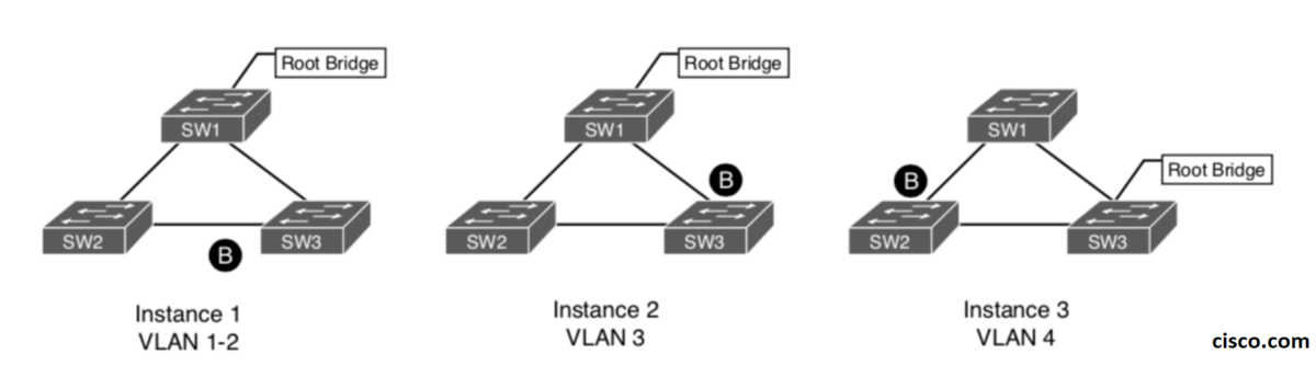
PVST (Per-VLAN Spanning Tree) is a Cisco proprietary extension of STP, which allows for multiple spanning trees, one for each VLAN. This means that each VLAN can have its own root bridge, which can help distribute the network traffic more efficiently.
MST (Multiple Spanning Tree) is an IEEE standard extension of STP, which provides a way to map multiple VLANs to a single spanning tree instance. MST allows network administrators to create multiple spanning trees that can be optimized for different groups of VLANs, thus providing better network efficiency and redundancy.
The main difference between STP, PVST, and MST is the number of spanning tree instances that can be used in a network. STP only supports one spanning tree instance per network, while PVST allows for multiple instances, one per VLAN. MST takes this one step further by allowing multiple VLANs to be mapped to a single instance.
MST Terminology and Topology Components
I- MST Instances:
An MST switch (bridge) mainly have two instances:
- One Internal Spanning Tree (IST)
- One or more Multiple Spanning Tree Instance(s) (MSTIs)
- Internal Spanning-Tree Instance (IST): Default spanning tree instance in any MST region. All VLANs in this IST instance conform a single spanning tree topology, allowing only one forwarding path between any two nodes. It also provides the root switch for any VLAN configured switches which are not specifically assigned to a MSTI.
MST uses a special instance, instance 0, called the internal spanning tree (IST). It is always the first instance and runs on all switch port interfaces in the MST region regardless of the VLANs associated with the ports.
- MSTI – Multiple Spanning Tree Instances: As MSTP enables grouping and mapping VLANs into different spanning tree instances, there’s an urge of determining a group or set of VLANs, which are all using the same spanning tree, this is what we come to know as a MSTI.
Unlike IST, this kind of instance comprises all static VLANs specifically assigned to it and at least, must include one VLAN.
Each instance defines a single forwarding topology for an exclusive set of VLANs, by contrast, STP or RSTP networks contains only a single spanning tree instance for the entire network, which contains all the VLANs.
MSTP allows frames/packets assigned to different VLANs to follow separate paths, each based on an independent MSTI, within MST Regions and MST Bridges:
II- MST Region:
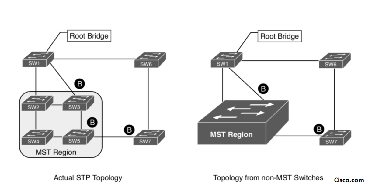
- MST Region: A group of MST switches with the same high-level configuration is known as an MST region. MST incorporates mechanisms that make an MST region appear as a single virtual switch to external switches.
- A set of interconnected switches that must have configured the same VLANs and MSTIs, also have the same following parameters:
- Switches must have the same MST configuration identification elements (region name, revision level and VLAN to MSTI mapping) to be in the same MST region. When configuring multiple MST regions for MSTP, MSTIs are locally significant within an MST region. MSTIs will not span from one region to another region.
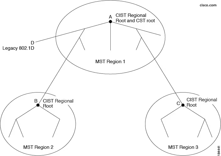
- Common Internal Spanning Tree (CIST): The common and internal spanning tree (CIST) is a single spanning tree that connects all devices in a switched network.
It consists of collection of ISTs in all MST regions. Every region needs to construct its own IST and When multiple regions connect together, MST should build one common CIST spanning across the regions. - The IST connects all the MST switches in the region and appears as a subtree in the CIST that encompasses the entire switched domain. The root of the subtree is the CIST regional root:
- Common Spanning Tree (CST):The MST Regions and the other Bridges in LANs are connected into a single Common Spanning Tree (CST).
The CST interconnects the MST regions and single spanning trees.
The common spanning tree (CST) is a single spanning tree that connects all MST regions. An entire region appears as one virtual bridge that runs a single spanning tree (CST). the CST is a spanning tree calculated by these devices through STP or RSTP.
The IST instance receives and sends BPDUs to the CST. The IST can represent the entire MST region as a CST virtual bridge to the outside world.
Each MST region is considered as a single bridge. CST interoperates with legacy IEEE STP/RSTP regions:
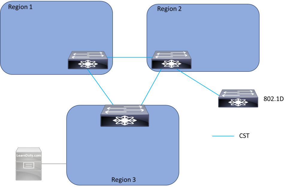
If there are multiple regions or 802.1D switches within the network, MST establishes and maintains the CST, which includes all MST regions and all 802.1D STP switches in the network. The MST instances combine with the IST at the boundary of the region to become the CST.
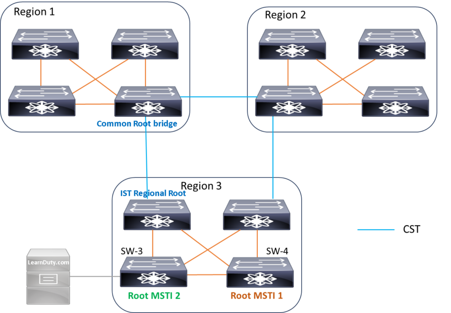
Regional root:
The root bridge of the IST or an MSTI within an MST region is the regional root of the IST or MSTI. Different spanning trees instances in an MST region might have different regional roots.
For example, In previous diagram, SW-3 is the regional root for MSTI2, but SW-4 is the Root bridge for MSTI1.
Common Root bridge:
The common root bridge is the root bridge of the CIST.
MST attributes and Region
Every switch that runs MST in the network has a configuration that consists of these three attributes:
- Region name: An alphanumeric configuration name (32 bytes)
- Revision number: A configuration revision number (two bytes)
- Instances to VLAN mapping: A 4096-element table that associates each of the potential 4096 VLANs supported on the chassis to a given instance
In order to be part of a common MST region, a group of switches must have the same configuration attributes. It is up to the network administrator to properly propagate the configuration throughout the region.
Region Boundary
First, The MST switch calculate a digest of the VLANs-to-instance mapping: a numerical value derived from the VLAN-to-instance mapping table through a mathematical function
This digest of the VLANs-to-instance mapping table is sent, along with the revision number and the name. Once a switch receives a BPDU, it extracts the digest and compares this digest with its own computed digest. If the digests differ, the port on which the BPDU was received is at the boundary of a region.
The exact VLANs-to-instance mapping is not propagated in the BPDU, because the switches only need to know whether they are in the same region as a neighbor.
MST Basic configuration
Step 1. Define MST as the spanning tree protocol with the command spanning-tree mode mst
Step 2. (Optional) Define MST instance priority, using one of two methods:
• spanning-tree mode mst instance-number priority priority
• spanning-tree mode mst instance-number root {primary | secondary} [diameter diameter]
(Note: Priority is a value between 0 and 61,440 in increments of 4096. The primary keyword
sets the priority to 24,576 and the secondary keyword sets the priority to 28,672.)
Step 3. Associate VLANs to an MST instance. By default, all VLANs are associated to the MST 0 instance. The MST configuration sub-mode must be entered with the command spanning-tree mst configuration. Then the VLANs are assigned to a different MST instance with the command instance instance-number vlan vlan-id.
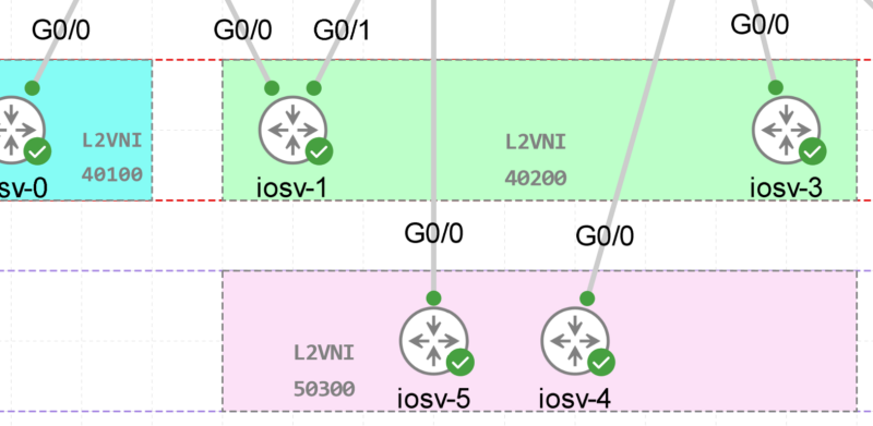
- Lab Topology:
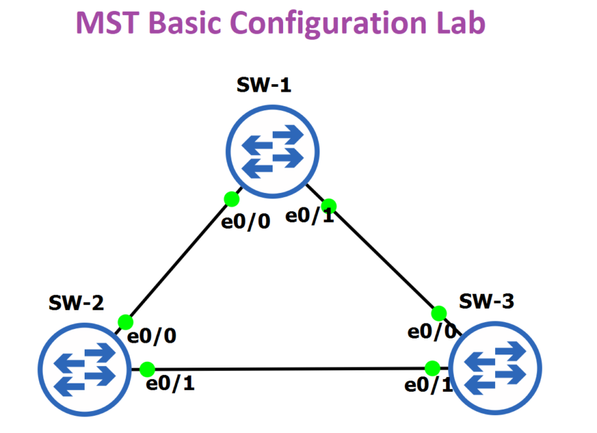
- Configuration:
vlan 10
vlan 20
vlan 30
vlan 40


interface Ethernet0/0
  switchport  trunk encapsulation dot1q
  switchport mode trunk
!
interface Ethernet0/1
  switchport  trunk encapsulation dot1q
  switchport mode trunk


spanning-tree mode mst

spanning-tree mst configuration

 name LearnDuty_REGION

 instance 1 vlan 10, 20

 instance 2 vlan 30, 40

!

spanning-tree mst 1 priority 8192
MST Regional Root:
MST BDPU Extension:
As stated in the previous section, MST uses RSTP for rapid convergence; therefore, each switch must be capable of processing RSTP BPDUs in order to support MST. The MST BPDU format is similar to that of RSTP. The primary difference is that the Protocol Version Identifier Field is 3 and the MST BPDUs contain an MST Extension field.
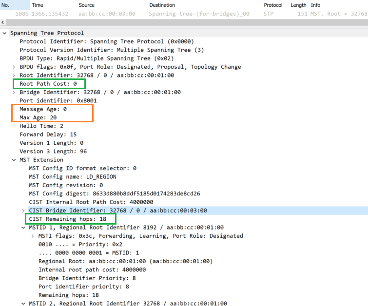
Hop Count:
MST uses the path cost to the root and a hop-count mechanism similar to the IP time-to-live (TTL) mechanism.
By using the spanning-tree mst max-hops global configuration command, you can configure the maximum hops inside the region and apply it to the IST and all MST instances in that region. The hop count achieves the same result as the message-age information (triggers a reconfiguration). The root bridge of the instance always sends a BPDU (or M-record) with a cost of 0 and the hop count set to the maximum value. When a switch receives this BPDU, it decrements the received remaining hop count by one and propagates this value as the remaining hop count in the BPDUs it generates. When the count reaches zero, the switch discards the BPDU and ages the information held for the port.
The message-age and maximum-age information in the RSTP portion of the BPDU remain the same throughout the region, and the same values are propagated by the region-designated ports at the boundary.
Reference:
cisco.com
arubanetworks.com
For more in depth:
![Explore The BGP Path Selection Attributes [Explained with Labs]](https://learnduty.com/wp-content/uploads/2022/07/image-28-800x450.png)