Data Plane Policing (DPP) in Cisco ACI [Explained and Configuration]
Reference: Notes from Cisco White paper
Contents
DPP in ACI Overview
Data Plane Policing monitors the data rates for a particular interface. DPP is used to manage bandwidth consumption on Cisco ACI fabric access interfaces. DPP policies can apply to egress traffic, ingress traffic, or both.
How DPP works:
When the data rate exceeds user-configured values, marking or dropping of packets occurs immediately. Policing does not buffer the traffic, therefore, the transmission delay is not affected.
Once the traffic exceeds the data rate, the Cisco ACI fabric can either:
- Drop the packets
- Mark QoS fields in the packet.
DPP Sharing mode in ACI:
Shared: If the sharing-mode is set to shared, then all the entities on the leaf switch referring to the same Data Plane Policer, will share the same hardware policer.
Dedicated: If the sharing-mode is set to dedicated then there would be a different HW policer allocated for each Layer 2 or Layer 3 or EPG member on the leaf switch. The policer is then dedicated to the entity that needs to be policed.
DPP types
DPP policies can be single-rate, dual-rate, and color-aware.
- Single-rate policies monitor the committed information rate (CIR) of traffic.
- Dual-rate policers monitor both CIR and peak information rate (PIR) of traffic. In addition, the system monitors associated burst sizes. Three colors, or conditions, are determined by the policer for each packet depending on the data rate parameters supplied: conform (green), exceed (yellow), or violate (red).
Note
The data plane does not police the packets transmitted from CPU and CPU bound packets on ACI fabric access interfaces, packet toward CPU are policed via CoPP
Data Plane Policing Configuration in ACI
Typically, DPP policies are applied to physical or virtual layer 2 connections for virtual or physical devices such as servers or hypervisors, and on layer 3 connections for routers.
- DPP policies applied to leaf switch access ports are configured in the fabric access (infra) portion of the Cisco ACI fabric.
- DPP policies applied to interfaces on border leaf switch access ports (l3extOut or l2extOut) are configured in the tenant (fvTenant) portion of the Cisco ACI fabric.
- The data plane policer can also be applied on an EPG so that traffic that enters the Cisco ACI fabric from a group of endpoints are limited per member access interface of the EPG. This is useful to prevent monopolization of any single EPG where access links are shared by various EPGs.
I- DPP for EPG:
The policing of the traffic is applied to all the EPG members on every leaf switch where the EPG is deployed.
Prior to the 3.2(1) release, each EPG member had its own policer. Beginning in the 3.2(1) release, the behavior is dependent on the sharing-mode property (if configured through the CLI or GUI) on the Data Plane Policer.
– If it is set to dedicated, then the situation is similar to before the 3.2(1) release.
– If the sharing-mode is set to shared, then all the members in the same slice using the same Data Plane Policer policy use the hardware policer on the leaf switch.
DPP for EPG Configuration steps:
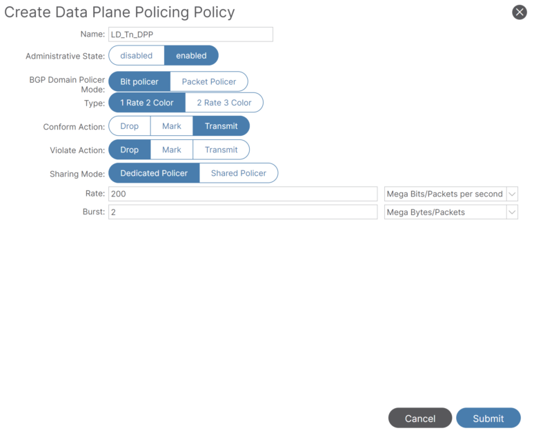
- Create DPP under the Tenant:
Navigate to: Tenant_name > Policies > Protocol > Data Plane Policing. Right-click on Data Plane Policing to Create Data Plane Policing Policy.
- Apply DDP to the EPG:
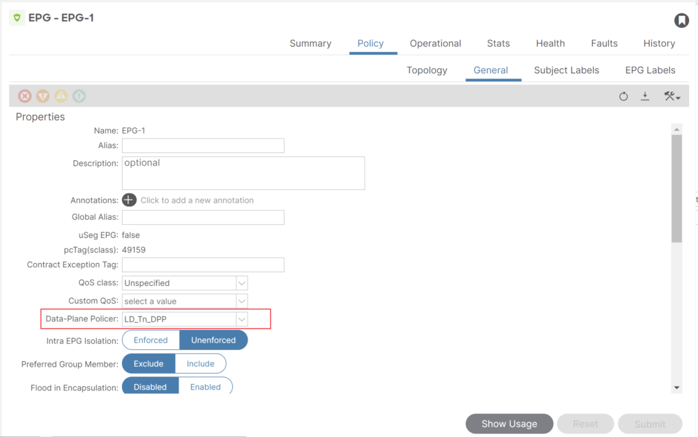
Let’s take an example, an EPG (EPG-1) has the following members:
- Leaf 101, Eth1/1, vlan-10
- Leaf 101, Eth1/2, vlan-30
- Leaf 102, Eth1/2, vlan-50
Shared: If the Data Plane Policer has the sharing-mode set to shared, then all the members in the same slice use only one policer on the leaf switch.
Dedicated: If the Data Plane Policer has the sharing-mode set to dedicated, each EPG members use its independent policer.
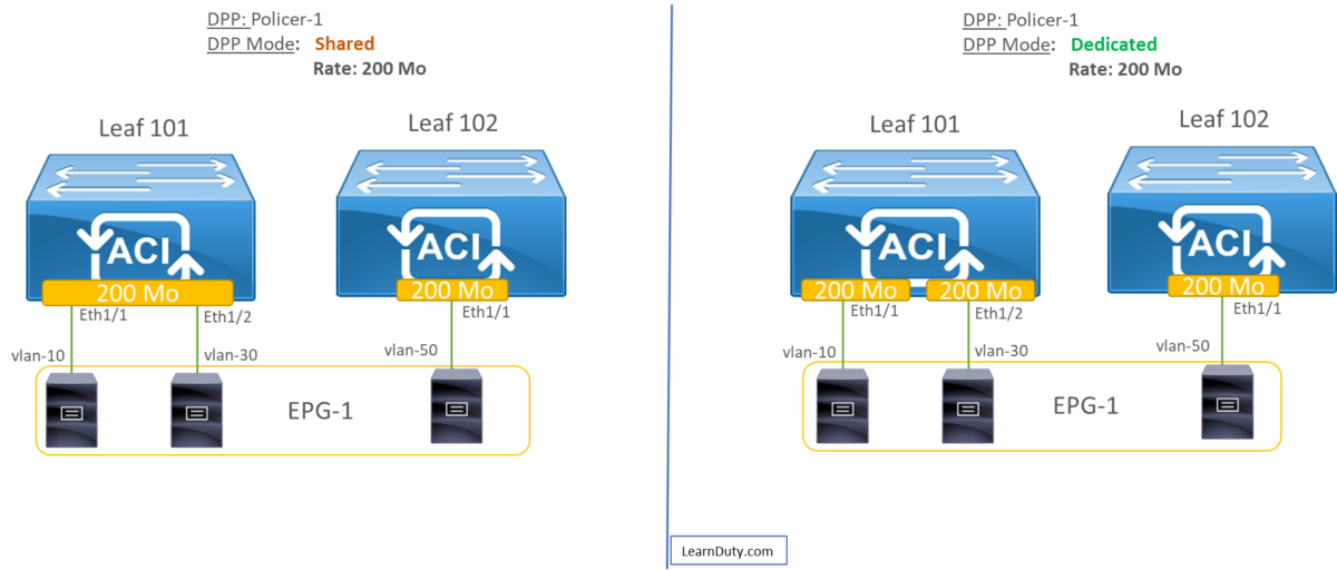
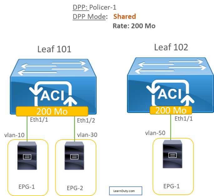
In case of DPP shared mode, policing is applied to Multiple EPGs on the same Leaf slice.
Example: Policer-A (200Mbps policing) applied to EPG1 and EPG2, 200Mbps is shared across EPGs using the same policer if the interfaces are in the same slice:
Scaling and Limitation for DPP applied on EPG:
The following are limitations for Data Plane Policing at the EPG level:
- EPG policer feature is supported with switch models that have -EX, -FX, or later.
- Egress traffic policing is not supported for the EPG level policer.
- Policer mode Packet-per-second is not supported.
- Policer type 2R3C is not supported in EPG policer.
- Policer is not supported when intra-EPG isolation-enforced is applied to the EPG.
- The scale limit allows for 128 EPG policers supported per node.
II- DPP For Layer 2 Interface:
1- Create DPP Policy:
Navigate to: Fabric > Access Policies > Policies > Interface > Data Plane Policing
Right-click and create new Data Plane Policing:
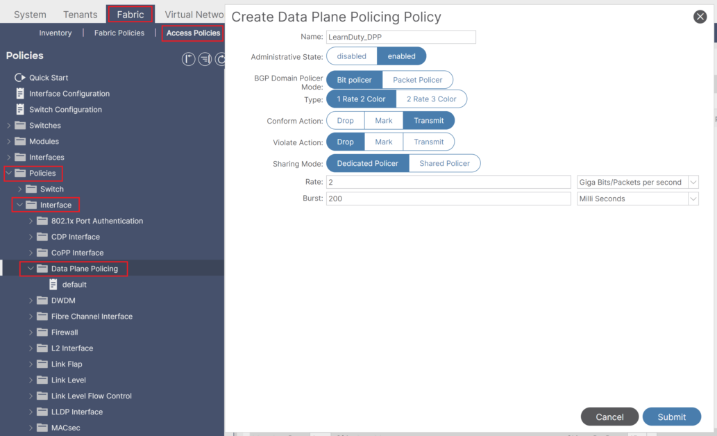
choose the conform and violate action:
- Drop: Drops the packets if the conditions are met.
- Mark: Marks the packets if the conditions are met.
- Transmit: Transmits the packets if the conditions are met.
If for Conform Action you chose Mark, perform the following substeps:
- For Conform mark CoS, enter the class of service for packets that conformed with the conditions.
- For Conform mark dscp, enter the differentiated services code point (DSCP) for packets that conformed with the conditions.
Sharing mode:
For Sharing Mode, choose Shared Policer.
- Shared Policer mode allows you to apply the same policing parameters to several interfaces simultaneously.
- The Dedicated Policer mode is not supported for Layer 2 interfaces.
For Rate, enter the rate at which to allow packets are allowed into the system and choose the unit per packet.
For Burst, enter the number of packets allowed at the line rate during a burst and choose the unit per packet.
If for Type you chose 2 Rate 3 Color, perform the following substeps:
- For Peak Rate, enter the peak information rate, which is the rate above which data traffic is negatively affected, and choose the unit per packet.
- For Excessive Burst, enter the size that a traffic burst can reach before all traffic exceeds the peak information rate, and choose the unit per packet.
2- Apply the DDP Policy to the Interface Policy Group:
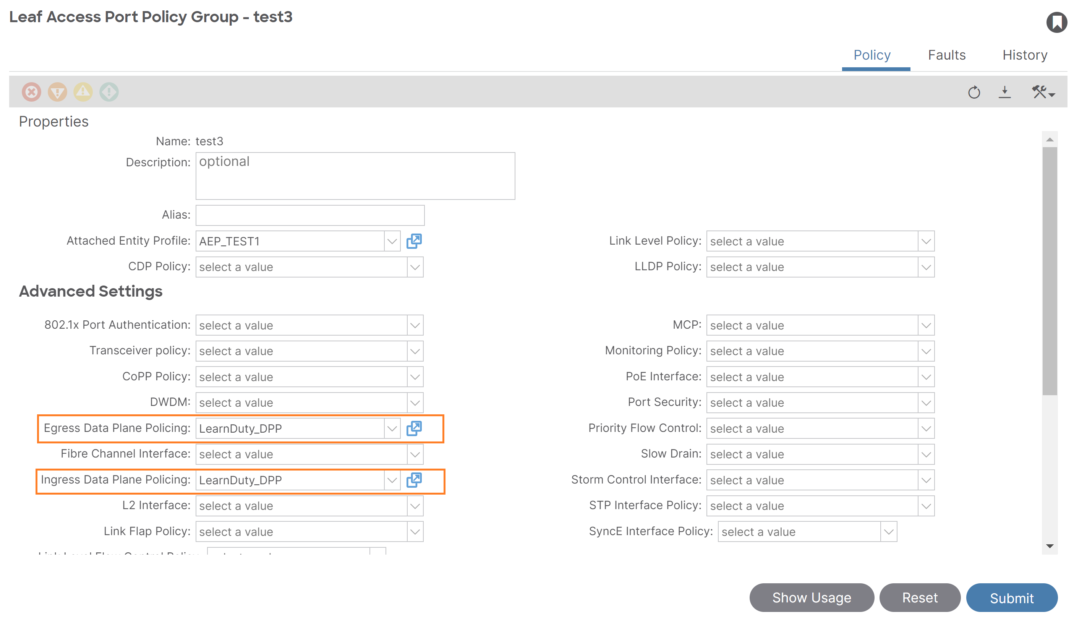
To apply the Layer 2 Data Plane Policing policy, the policy must be added to a policy group and the policy group must be mapped to an interface profile that serve as L2:
The Data Plane Policing can be applied to ingress, egress or both:
III- DPP For Layer 3 Interface:
Navigate to Tenant_name > Networking > L3Outs > L3Out_name > Logical Node Profiles > Logical Interface Profiles:

Create a DPP Policy and Apply it to ingress or egress on the logical Interface profile:
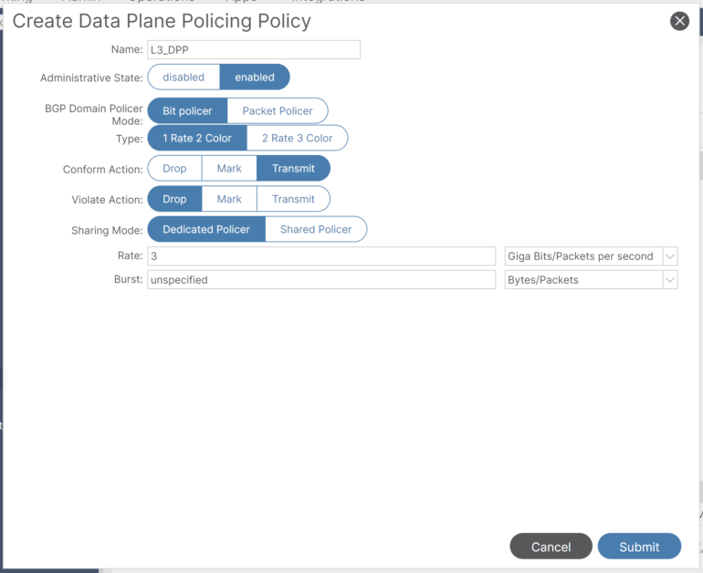
The Data Plane Policing policy must be added to a policy group and the policy group mapped to an interface profile to apply the L3 DPP policy.

