Cisco ACI Multi-site Initial Setup Configuration on Nexus Dashboard Orchestrator
Contents
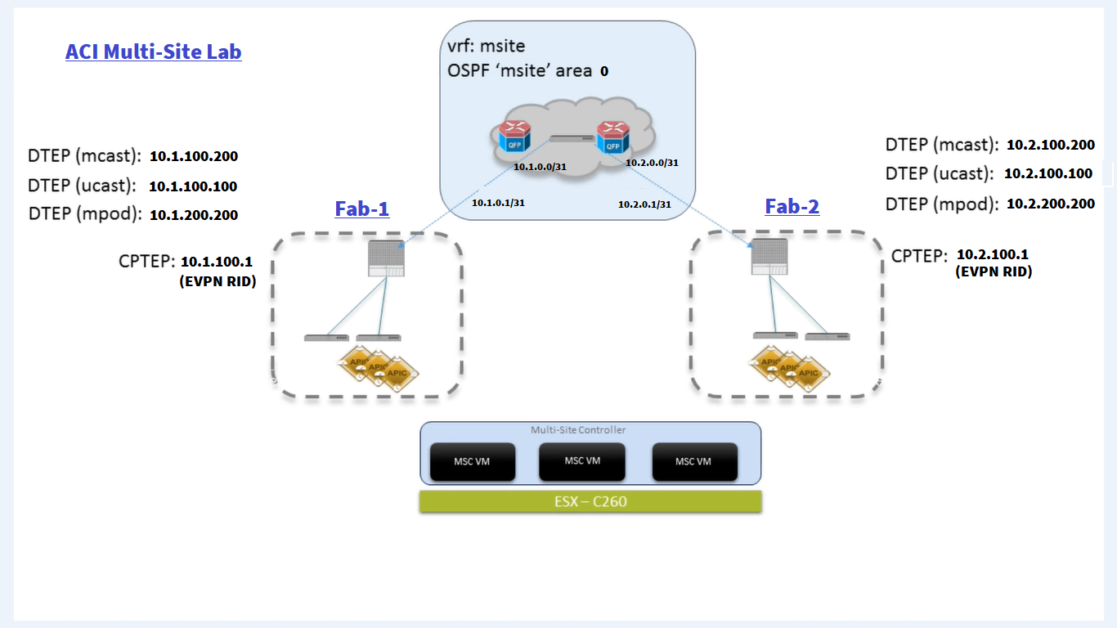
Topology:
This Lab is based on Dcloud resources:
- Nexus Dashboard
- ACI Simulators
We will go through the day 0 configuration for ACI Multi-site:
I- Add sites to Nexus Dashboard
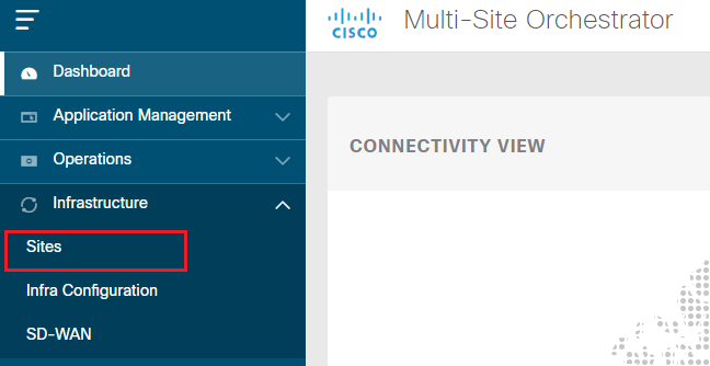
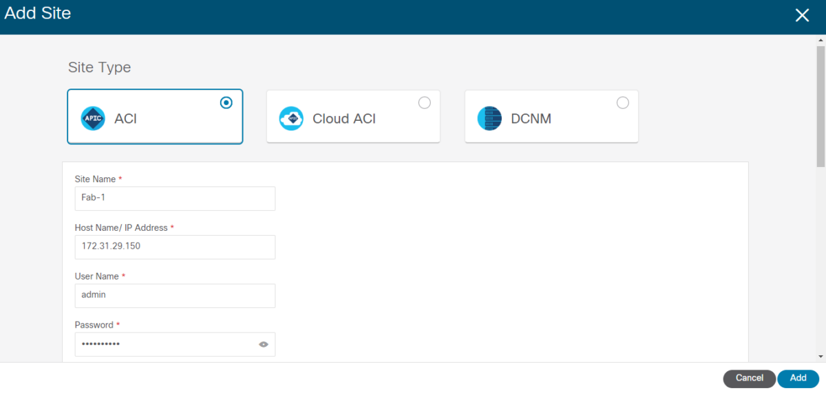
After adding the site to the Cisco Nexus Dashboard (NDO), you must move them into a managed state in the Multi-Site Orchestrator (MSO).
In MSO, under Infrastructure > Sites, we will see the sites added via ND in Unmanaged state:
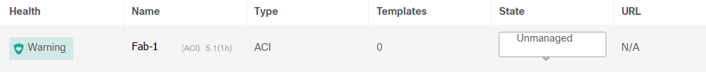
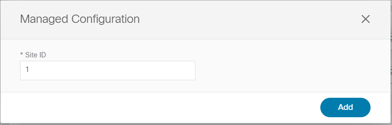
Select Managed and chose the site ID to assign to the selected site:
II- Day-0 Infrastructure Configuration
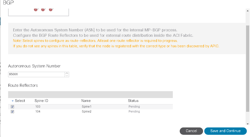
1- Make sure BGP Route Reflector Configuration is done on each site:
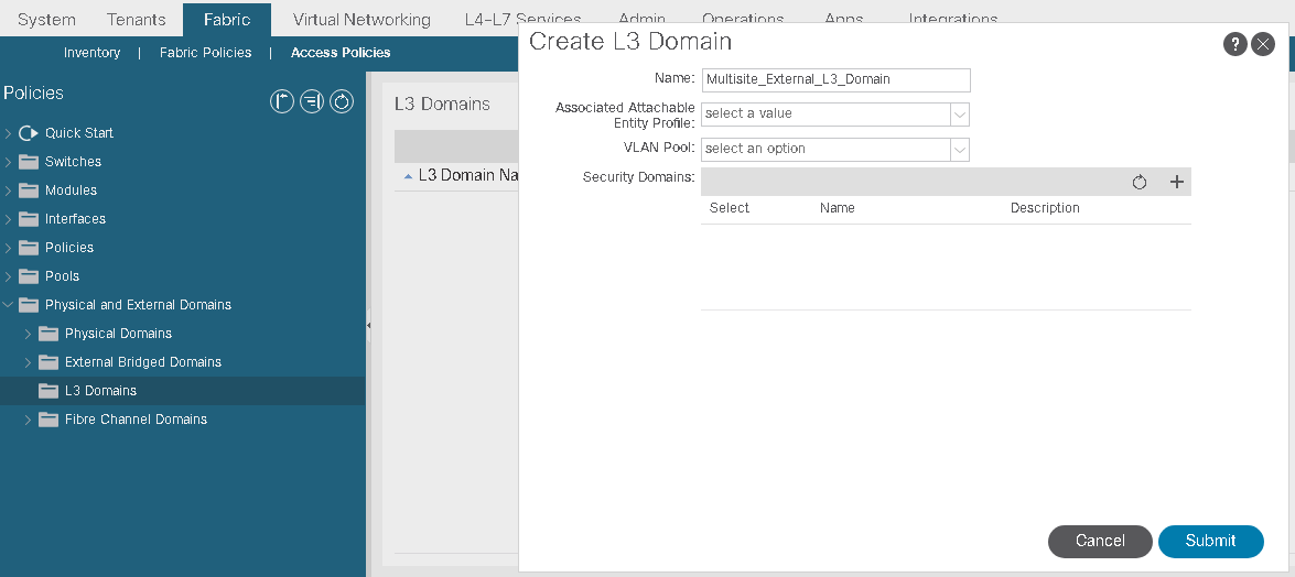
2- L3Domain for Multi-site
ON each Site navigate to: Under Fabric > Access Policies > Create a L3Domain:
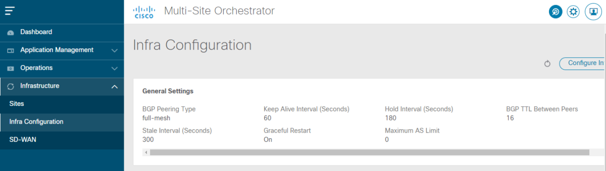
3- BGP and OSPF Infra Configuration:
- In MSO, Under Infrastructure > Infra Configuration:
- Click on Configure Infra then select Site to configure, We will start with Spine1 Interfaces configuration:
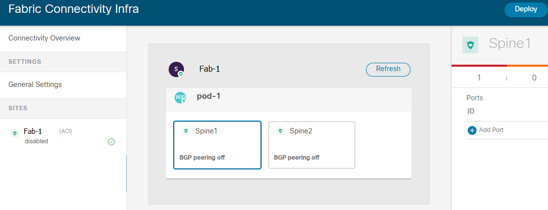
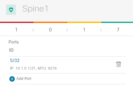
- Click on Spine1 and Add Port:
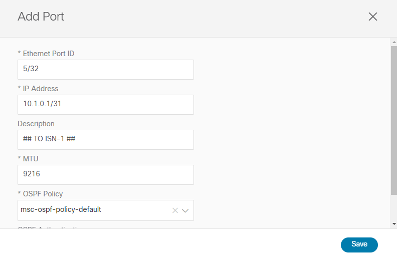
- Click on Save:
only a few of prefixes are required for establishing intersite control and data plane connectivity:
- A BGP EVPN Router-ID (CTEP): for each spine node, to establish MP-BGP EVPN adjacencies to remote spine nodes.
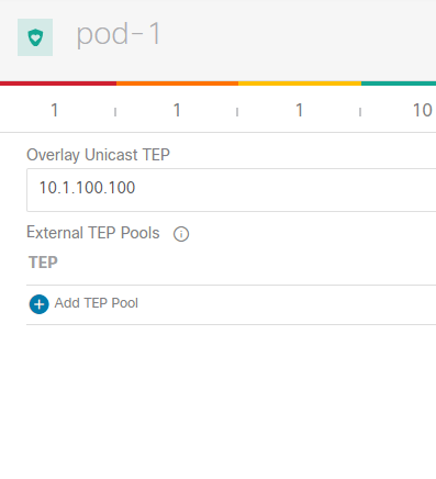
- An Overlay Unicast TEP (O-UTEP): anycast address for each Pod part of the same ACI fabric, used for unicast Layer 2 and Layer 3 data plane connectivity with the remote sites.
- An Overlay Multicast TEP (O-MTEP): anycast address shared between all the Pods part of the same ACI fabric, used to receive Layer 2 Broadcast/Unknown Unicast/Multicast (BUM) traffic originated from the remote sites.
- One (or more) external TEP pools are used to enable the intersite L3Out connectivity with the remote sites.
The original infra TEP pools used for each fabric bring-up do not need to be exchanged across sites.
BGP EVPN Router-ID:
- Toggle the button to enable BGP Peering and enter the BGP-EVPN Router RID for the Spine:
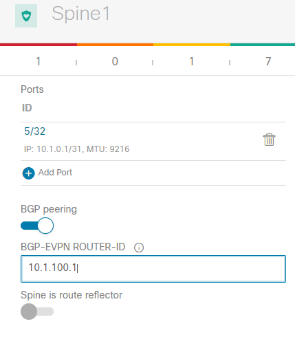
Inter-site control plane: Endpoint reachability information is exchanged across sites using a Multiprotocol-BGP (MP-BGP) Ethernet VPN (EVPN) control plane. This approach allows the exchange of MAC and IP address information for the endpoints that communicate across sites. MP-BGP EVPN sessions are established between the spine nodes deployed in separate fabrics.
- Configure Dataplane UNICAST TEP (O-UTEP):
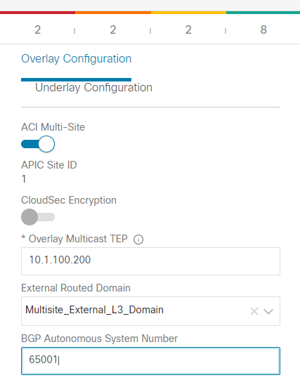
- Complete the Underlay and Overlay configuration for the site:
Overlay Multicast TEP and select:
- External Routed Domain
- ASN
- Overlay Multicast TEP
OSPF Area ID and Type (With ISN):
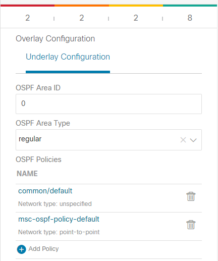
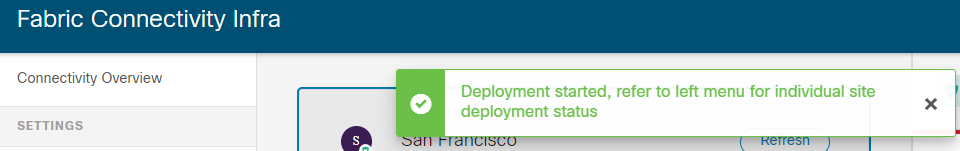
Click on Deploy:
On the APIC of each site, in the Infra Tenant, we can verify the configuration pushed from the MSO to the APIC:
First thing, we notice that there is a notice about the fact that this object configuration was done via MSO:
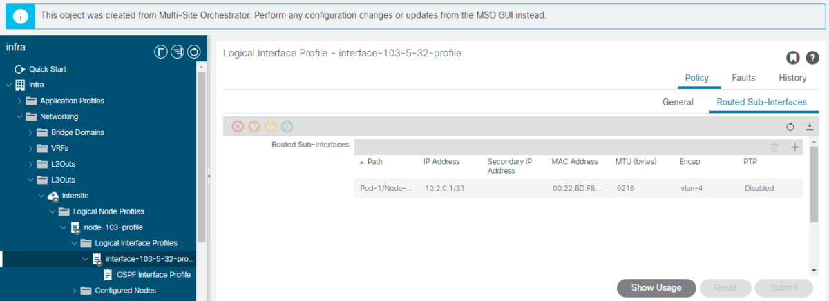
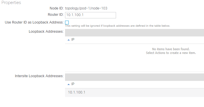
The router ID of the Spine was configured according to MSO inputs:
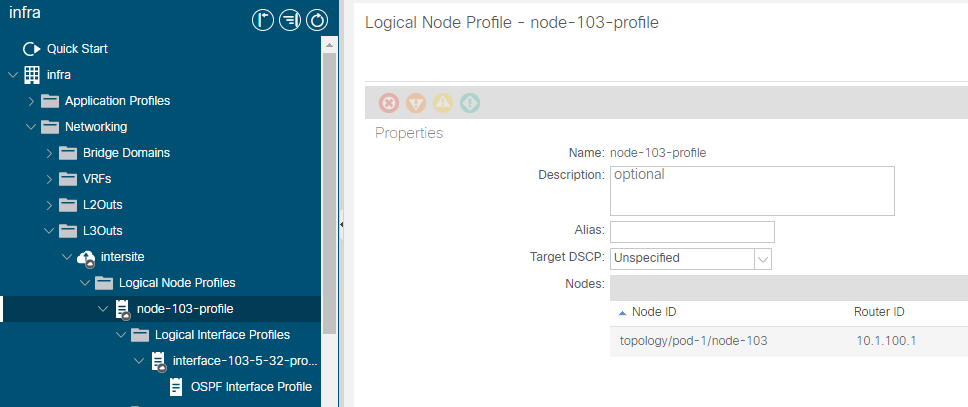
We can see that the Router-ID is also configured as Intersite Loopback:
Also, the BGP peer was configured to the other site Spine Router-ID:

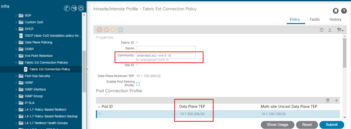
4- Add the Multipod Data Plane TEP configuration (known as ETEP):
The Multipod Dataplane TEP represents the next-hop for all the EVPN prefixes (MAC and IP addresses for locally discovered endpoints) advertised between pods.
Navigate to Tenants > infra > Policies > Protocol > Fabric Ext Connections Policies and click Fabric Ext Connection Policy.
Verification from spine level:
spine-1# show ip int vrf overlay-1Code language: PHP (php)DCI-UCAST (O-UTEP): This anycast Data plane ETEP address is unique per Pod in fabric. It is assigned to all the spines in same Pod connected to the IPN/ISN device and used to receive L2/L3 unicast traffic.
DCI-MCAST-HREP (O-MTEP): This anycast ETEP address is assigned to all the spines connected to the IPN/ISN device and used to receive L2 BUM (Broadcast, Unknown unicast and Multicast) traffic.
MSCP-ETEP (Multi-Site Control-plane ETEP): This is the control plane ETEP address, which is also known as BGP Router ID on each spine for MP-BGP EVPN.
ETEP (Multipod Dataplane TEP): The Dataplane Tunnel Endpoint address used to route traffic between multiple Pods within the single ACI fabric.