
IP Multicast Basics
Contents
Introduction:
Traditional IP communication allows a host to send packets to a single host (unicast transmission) or to all hosts (broadcast transmission). IP multicast provides a third possibility: allowing a host to send packets to a subset of all hosts as a group transmission.
Why do we need Multicast:
IP multicast is a bandwidth-conserving technology that reduces traffic by simultaneously delivering a single stream of information to potentially thousands of corporate recipients and homes. Applications that take advantage of multicast include video conferencing, corporate communications, distance learning, and distribution of software, stock quotes, and news.
IP multicast delivers application source traffic to multiple receivers without burdening the source or the receivers while using a minimum of network bandwidth. Multicast packets are replicated in the network at the point where paths diverge by Cisco routers enabled with Protocol Independent Multicast (PIM) and other supporting multicast protocols, resulting in the most efficient delivery of data to multiple receivers.
Multicast terminology and concepts:
1- Multicast Group:
Multicast is based on the concept of a group. A multicast group is an arbitrary group of receivers that expresses an interest in receiving a particular data stream. This group has no physical or geographical boundaries, the hosts can be located anywhere on the Internet or any private internetwork. Hosts that are interested in receiving data flowing to a particular group must join the group using IGMP.
Hosts must be a member of the group to receive the data stream.
2- IP Multicast Addresses
IP multicast addresses specify a “set” of IP hosts that have joined a group and are interested in receiving multicast traffic designated for that particular group.
The Internet Assigned Numbers Authority (IANA) controls the assignment of IP multicast addresses. IANA has assigned the IPv4 Class D address space to be used for IP multicast. Therefore, all IP multicast group addresses fall in the range from 224.0.0.0 through 239.255.255.255.
Multicast Address Range Assignments:
| Description | Range |
|---|---|
| Reserved Link Local Addresses | 224.0.0.0/24 |
| Globally Scoped Addresses | 224.0.1.0 to 238.255.255.255 |
| Source Specific Multicast | 232.0.0.0/8 |
| GLOP Addresses | 233.0.0.0/8 |
| Limited Scope Addresses | 239.0.0.0/8 |
- Reserved Link Local Addresses: sed by network protocols on a local network segment. Packets with these addresses should never be forwarded by a router. Packets with link local destination addresses are typically sent with a time-to-live (TTL) value of 1 and are not forwarded by a router.
- Globally Scoped Addresses: Addresses in the range from 224.0.1.0 through 238.255.255.255 are called globally scoped addresses. These addresses are used to multicast data between organizations and across the Internet. Some of these addresses have been reserved for use by multicast applications through IANA. For example, IP address 224.0.1.1 has been reserved for Network Time Protocol (NTP).
- Source Specific Multicast Addresses: Addresses in the 232.0.0.0/8 range are reserved for Source Specific Multicast (SSM). SSM is an extension of the PIM protocol that allows for an efficient data delivery mechanism in one-to-many communications.
- GLOP Addresses: reserved for statically defined addresses by organizations that already have an AS number reserved. This practice is called GLOP addressing. The AS number of the domain is embedded into the second and third octets of the 233.0.0.0/8 address range. For example, the AS 62010 is written in hexadecimal format as F23A. Separating the two octets F2 and 3A results in 242 and 58 in decimal format. These values result in a subnet of 233.242.58.0/24 that would be globally reserved for AS 62010 to use.
- Limited Scope Addresses: These addresses are described in RFC 2365, Administratively Scoped IP Multicast, to be constrained to a local group or organization. Companies, universities, or other organizations can use limited scope addresses to have local multicast applications that will not be forwarded outside their domain. Routers typically are configured with filters to prevent multicast traffic in this address range from flowing outside of an autonomous system (AS) or any user-defined domain. Within an autonomous system or domain, the limited scope address range can be further subdivided so that local multicast boundaries can be defined. This subdivision is called address scoping and allows for address reuse between these smaller domains.
3- Multicast Distribution Trees:
Multicast-capable routers create distribution trees that control the path that IP multicast traffic takes through the network in order to deliver traffic to all receivers. The two basic types of multicast distribution trees are source trees and shared trees, which are described in the following sections.
Source Trees:
The simplest form of a multicast distribution tree is a source tree with its root at the source and branches forming a spanning tree through the network to the receivers. Because this tree uses the shortest path through the network, it is also referred to as a shortest-path tree (SPT).
Figure below shows an example of an SPT for group 224.1.1.1 rooted at the source, Host A, and connecting two receivers, Hosts B and C.
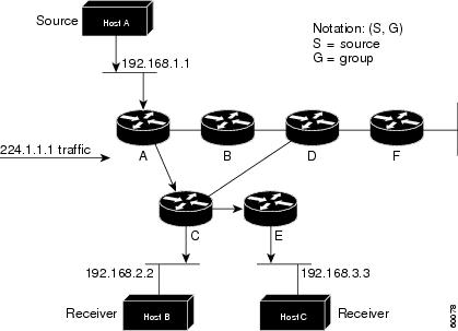
The special notation of (S, G), pronounced “S comma G,” enumerates an SPT where S is the IP address of the source and G is the multicast group address. Using this notation, the SPT for the example shown in the previous figure would be (192.168.1.1, 224.1.1.1).
The (S, G) notation implies that a separate SPT exists for each individual source sending to each group—which is correct. For example, if Host B is also sending traffic to group 224.1.1.1 and Hosts A and C are receivers, a separate (S, G) SPT would exist with a notation of (192.168.2.2, 224.1.1.1).
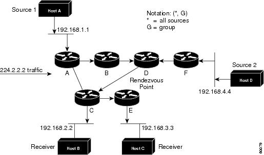
Unlike source trees that have their root at the source, shared trees use a single common root placed at some chosen point in the network. This shared root is called a Rendezvous Point (RP).
Figure below shows a shared tree for the group 224.2.2.2 with the root located at Router D. This shared tree is unidirectional. Source traffic is sent towards the RP on a source tree. The traffic is then forwarded down the shared tree from the RP to reach all of the receivers (unless the receiver is located between the source and the RP, in which case it will be serviced directly).
Multicast forwarding Basics:
In unicast routing, traffic is routed through the network along a single path from the source to the destination host. A unicast router does not consider the source address; it considers only the destination address and how to forward the traffic toward that destination. The router scans through its routing table for the destination address and then forwards a single copy of the unicast packet out the correct interface in the direction of the destination.
In multicast forwarding, the source is sending traffic to an arbitrary group of hosts that are represented by a multicast group address. The multicast router must determine which direction is the upstream direction (toward the source) and which one is the downstream direction (or directions). If there are multiple downstream paths, the router replicates the packet and forwards it down the appropriate downstream paths (best unicast route metric)—which is not necessarily all paths. Forwarding multicast traffic away from the source, rather than to the receiver, is called Reverse Path Forwarding (RPF). RPF is described in the following section.
Reverse Path Forwarding (RPF)
PIM uses the unicast routing information to create a distribution tree along the reverse path from the receivers towards the source. The multicast routers then forward packets along the distribution tree from the source to the receivers. RPF is a key concept in multicast forwarding. It enables routers to correctly forward multicast traffic down the distribution tree. RPF makes use of the existing unicast routing table to determine the upstream and downstream neighbors. A router will forward a multicast packet only if it is received on the upstream interface. This RPF check helps to guarantee that the distribution tree will be loop-free.
RPF Check
When a multicast packet arrives at a router, the router performs an RPF check on the packet. If the RPF check succeeds, the packet is forwarded. Otherwise, it is dropped.
For traffic flowing down a source tree, the RPF check procedure works as follows:
1. The router looks up the source address in the unicast routing table to determine if the packet has arrived on the interface that is on the reverse path back to the source.
2. If the packet has arrived on the interface leading back to the source, the RPF check succeeds and the packet is forwarded.
3. If the RPF check in Step 2 fails, the packet is dropped.
- Example of unsuccessful RPF check:
The figure below shows an example of an unsuccessful RPF check:
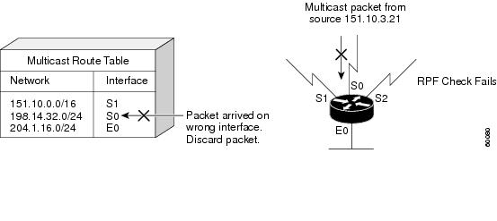
A multicast packet from source 151.10.3.21 is received on serial interface 0 (S0). A check of the unicast route table shows that S1 is the interface this router would use to forward unicast data to 151.10.3.21. Because the packet has arrived on interface S0, the packet is discarded.
- Example of successful RPF check:
The figure below shows an example of a successful RPF check.
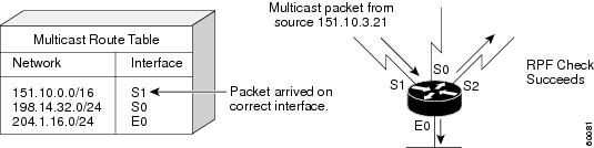
In this example, the multicast packet has arrived on interface S1. The router refers to the unicast routing table and finds that S1 is the correct interface. The RPF check passes, and the packet is forwarded.
Reference (reformed from):
https://www.cisco.com/c/en/us/td/docs/ios/solutions_docs/ip_multicast/White_papers/mcst_ovr.html#wp1009024
![OSPF DR and BDR Election Explained [with Configuration]](https://learnduty.com/wp-content/uploads/2022/03/image-33.png?v=1647900046)
![OSPF Neighbor Adjacency Requirements [With Configuration]](https://learnduty.com/wp-content/uploads/2022/03/image-23-418x450.png?v=1647900064)
![OSPF Neighbor States Explained [Step by Step]](https://learnduty.com/wp-content/uploads/2022/03/image-13.png?v=1647900076)
![OSPF Area Types Explained and Configuration [Demystified]](https://learnduty.com/wp-content/uploads/2022/03/image-8.png?v=1647900083)