Remote SPAN (RSPAN) Configuration Example
Contents
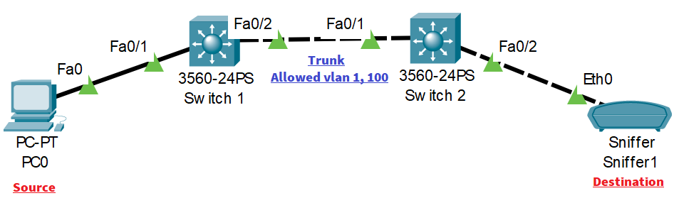
Remote Switched Port Analyzer Topology
Remote SPAN (RSPAN) Configuration (Step by Step)
Step-1: Remote-Span VLAN configuration
First of all, we need to configure the Remote-Span VLAN configuration on all switches between the source and destination device.
We will use VLAN 100 as a remote-span VLAN in our case:
On switch1:
Switch(config)#hostname Switch1
Switch1(config)#vlan 100
Switch1(config-vlan)#remote-span
On switch2:
Switch(config)#hostname Switch2
Switch2(config)#vlan 100
Switch2(config-vlan)#remote-span
Step-2: Allow the remote-span VLAN in the trunk link between the switches:
The remote span VLAN should be defined and allowed on all switches between the source and destination SPAN.
On switch1:
Switch1(config)#int fa0/2
Switch1(config-if)#switchport trunk encapsulation dot1q
Switch1(config-if)#switchport mode trunk
Switch1(config-if)#
%LINEPROTO-5-UPDOWN: Line protocol on Interface FastEthernet0/2, changed state to down

%LINEPROTO-5-UPDOWN: Line protocol on Interface FastEthernet0/2, changed state to up

Switch1(config-if)#switchport trunk allowed vlan 1,100
On switch2:
Switch2(config-if)#int fa0/1
Switch2(config-if)#switchport trunk encapsulation dot1q
Switch2(config-if)#switchport mode trunk
Switch1(config-if)#
%LINEPROTO-5-UPDOWN: Line protocol on Interface FastEthernet0/1, changed state to down

%LINEPROTO-5-UPDOWN: Line protocol on Interface FastEthernet0/1, changed state to up
Switch2(config-if)#switchport TRunk allowed vlan 1,100
Step-3: Configure the monitor session:
On switch1:
The RSPAN monitor session source configuration is the same as local SPAN:
Switch1(config)#monitor session 1 source interface Fa0/1
The RSPAN monitor session destination configuration should point to remote span VLAN:
Switch1(config)#monitor session 1 destination ?
  interface  SPAN source or destination interface
  remote     RSPAN

Switch1(config)#monitor session 1 destination remote vlan 100
%SYS-5-CONFIG_I: Configured from console by console
On switch2:
On the switch on which the destination SPAN resides, the remote VLAN will be configured as the source SPAN and the destination is the interface facing the sniffer.
Switch2(config)#monitor session 1 source remote vlan 100
Switch2(config)#monitor session 1 destination interface fa0/2
Remote SPAN (RSPAN) Verification
On switch1:
Switch1#show monitor session 1
Session 1
---------
Type                   : Remote Destination Session
Description            : -
Source Ports           :
    Both               : Fa0/1
Dest RSPAN VLAN        : 100
On switch2:
Switch2#show monitor session 1
Session 1
---------
Type                   : Remote Source Session
Description            : -
Source RSPAN VLAN      : 100
Destination Ports      : Fa0/2
    Encapsulation      : Native
          Ingress      : Disabled
We start a ping from PC to interface VLAN on switch1:
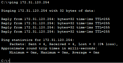
The Sniffer device connected to the interface Fa0/2 on switch2 is receiving the ICMP traffic.
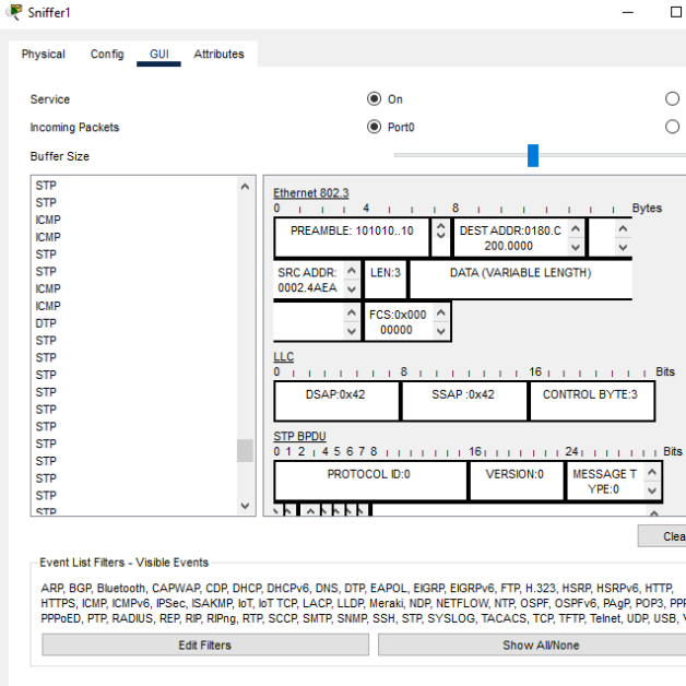
Verified!
![Explore The BGP Path Selection Attributes [Explained with Labs]](https://learnduty.com/wp-content/uploads/2022/07/image-28-800x450.png)