LACP Port Channel Explained (Link Aggregation Deep Dive)
Contents
What is Link Aggregation:
Link aggregation is the combining of multiple network connections in parallel by any of several methods, in order to increase throughput beyond what a single connection could sustain, to provide redundancy in case one of the links should fail.
LACP ( Link Aggregation Control Protocol)
Within the IEEE Ethernet standards, the Link Aggregation Control Protocol (LACP) provides a method to control the bundling of several physical links together to form a single logical link. LACP allows a network device to negotiate an automatic bundling of links by sending LACP packets to their peer, a directly connected device that also implements LACP.
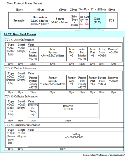
LACPDU Frame:
- Maximum number of bundled ports allowed in the port channel: Valid values are usually from 1 to 8.
- LACP packets are sent with multicast group MAC address 01:80:C2:00:00:02 (slow protocols)
- During LACP detection period
- LACP packets are transmitted every second
- Keep-alive mechanism for link member: (default: slow = 30s, fast=1s)
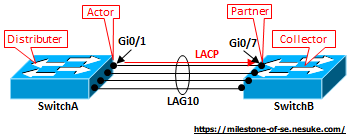
The LACP transmission device is called Distributor (meaning that load balances and passes frames):
- Actor: is the LACP sending interface (transmitting device).
- Partner: is the LACP receiving interface (counterpart device).
- Collector (collecting load-balanced frames) is the LACP counterparty device .
- Terminator marks his LACP frame termination.
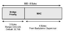
- System priority (LACP system ID):
The LACP logic uses a system priority value, which is generated by the combination of the device MAC address with a user-configurable two-octet priority parameter.
System priority is used to determine the device (with higher priority) responsible to select the ports to aggregate in a bundle (port channel).
- To check the LACP sys-id priority value:
Switch#show lacp sys-id
32768, 5254.0003.8000- To configure the LACP priority value:
switch(config)# lacp system-priority 1Priority 1 will make the switch the device with higher priority (because it has the lowest priority value)
The system that has higher system LACP priority sets the Selected state of member ports on its side first and then the system that has lower priority sets the port state accordingly.
The switch with the lowest system priority value will be preferred
- Port aggregation priority
The device with the higher system priority is entitled to choose which ports to join the port channel. the selection of these ports is based on the port aggregation priority value.
The port aggregation priority value is generated by the combination of the port number with a user-configurable two-octet priority parameter.
The values for both user-configurable priority parameters can vary from 1 to 65535. Their default configuration is 32768. A port with a lower priority number is preferred.
The interface priority can be set in interface configuration mode, with the command:
interface gi0/0
lacp port-priority 1
Note: For system priority and port priority, the smaller the priority value, the higher the Priority.
LACP Parameters
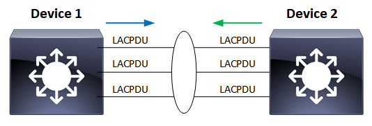
LACP Negotiation Process
When Device-1 receives LACPDUs from Device 2, Device 2 checks TLVs information about Device 1 and compares LACP system priorities:
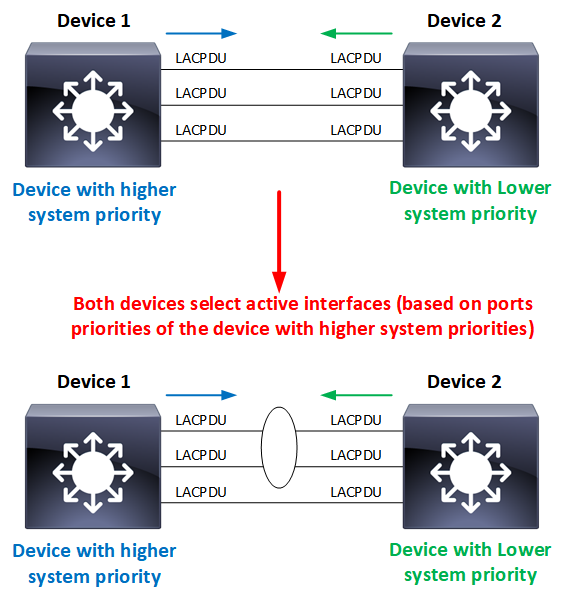
Both devices select active interfaces based on the interface priorities of the device with higher system priority. If the priorities of interfaces are the same, interfaces with lower interface numbers are selected as active interfaces.
When LACP is configured on ports, it tries to configure the maximum number of compatible ports in a port channel, up to the maximum allowed by the hardware (four ports). If LACP cannot aggregate all the ports that are compatible (for example, the remote system might have more restrictive hardware limitations), then all the ports that cannot be actively included in the channel are put in the hot standby state and are used only if one of the channeled ports fails.
A port channel is UP once both devices select the same interfaces as active interfaces.
LACP Debug
- Active Device:
*Nov 21 15:06:51.186: LACP: lacp_send_lacp_off: (Et0/0) About to send the 110 LACPDU
*Nov 21 15:06:51.186: LACP :lacp_bugpak: Send LACP-PDU packet via Et0/0
*Nov 21 15:06:51.186: LACP : packet size: 128
*Nov 21 15:06:51.186: LACP: pdu: subtype: 1, version: 1
*Nov 21 15:06:51.186: LACP: Act: tlv:1, tlv-len:20, key:0x100A, p-pri:0x8000, p:0x1, p-state:0x41,
s-pri:0x8000, s-mac:aabb.cc00.0100
*Nov 21 15:06:51.186: LACP: Part: tlv:2, tlv-len:20, key:0x0, p-pri:0x0, p:0x0, p-state:0x0,
s-pri:0x0, s-mac:0000.0000.0000
*Nov 21 15:06:51.186: LACP: col-tlv:3, col-tlv-len:16, col-max-d:0x8000
*Nov 21 15:06:51.186: LACP: term-tlv:0 termr-tlv-len:0
*Nov 21 15:06:51.186: LACP: lacp_write: LACP 128 bytes out Et0/0


*Nov 21 15:06:55.058: LACP :lacp_bugpak: Receive LACP-PDU packet via Et0/0
*Nov 21 15:06:55.058: LACP : packet size: 124
*Nov 21 15:06:55.058: LACP: pdu: subtype: 1, version: 1
*Nov 21 15:06:55.058: LACP: Act: tlv:1, tlv-len:20, key:0xA, p-pri:0x8000, p:0x1, p-state:0x6,
s-pri:0x8000, s-mac:aabb.cc00.0200
*Nov 21 15:06:55.058: LACP: Part: tlv:2, tlv-len:20, key:0xA, p-pri:0x8000, p:0x1, p-state:0xC7,
s-pri:0x8000, s-mac:aabb.cc00.0100
*Nov 21 15:06:55.058: LACP: col-tlv:3, col-tlv-len:16, col-max-d:0x8000
IOU2#
*Nov 21 15:06:55.270: LACP: col-tlv:3, col-tlv-len:16, col-max-d:0x8000
*Nov 21 15:06:55.270: LACP: term-tlv:0 termr-tlv-len:0
*Nov 21 15:06:55.270: LACP: lacp_write: LACP 128 bytes out Et0/1
*Nov 21 15:06:55.270:     lacp_ptx Et0/1 - ptx: during state PERIODIC_TX, got event 4(short_timeout)
*Nov 21 15:06:55.270: @@@ lacp_ptx Et0/1 - ptx: PERIODIC_TX -> FAST_PERIODIC

*Nov 21 15:06:55.926: LACP: lacp_send_lacpdu: (Et0/0) About to send the 110 LACPDU
*Nov 21 15:06:55.926: LACP :lacp_bugpak: Send LACP-PDU packet via Et0/0
*Nov 21 15:06:55.926: LACP : packet size: 128
*Nov 21 15:06:55.926: LACP: pdu: subtype: 1, version: 1
*Nov 21 15:06:55.926: LACP: Act: tlv:1, tlv-len:20, key:0xA, p-pri:0x8000, p:0x1, p-state:0x7,
s-pri:0x8000, s-mac:aabb.cc00.0100
*Nov 21 15:06:55.926: LACP: Part: tlv:2, tlv-len:20, key:0xA, p-pri:0x8000, p:0x1, p-state:0x6,
s-pri:0x8000, s-mac:aabb.cc00.0200
*Nov 21 15:06:55.926: LACP: col-tlv:3, col-tlv-len:16, col-max-d:0x8000
*Nov 21 15:06:55.926: LACP: term-tlv:0 termr-tlv-len:0
*Nov 21 15:06:55.926: LACP: lacp_write: LACP 128 bytes out Et0/0- Passive Device:
IOU3(config-if-range)#
*Nov 21 15:06:51.138: LACP :lacp_bugpak: Receive LACP-PDU packet via Et0/0
*Nov 21 15:06:51.138: LACP : packet size: 124
*Nov 21 15:06:51.138: LACP: pdu: subtype: 1, version: 1
*Nov 21 15:06:51.138: LACP: Act: tlv:1, tlv-len:20, key:0x100A, p-pri:0x8000, p:0x1, p-state:0x41,
s-pri:0x8000, s-mac:aabb.cc00.0100
*Nov 21 15:06:51.138: LACP: Part: tlv:2, tlv-len:20, key:0x0, p-pri:0x0, p:0x0, p-state:0x0,
s-pri:0x0, s-mac:0000.0000.0000
*Nov 21 15:06:51.138: LACP: col-tlv:3, col-tlv-len:16, col-max-d:0x8000
*Nov 21 15:06:51.138: LACP: term-tlv:0 termr-tlv-len:0
*Nov 21 15:06:51.138: LACP: Et0/0 LACP packet received, processing
*Nov 21 15:06:51.138:     lacp_rx Et0/0 - rx: during state PORT_DISABLED, got event 5(recv_lacpdu) (ignored)
*Nov 21 15:06:51.154: LACP :lacp_bugpak: Receive LACP-PDU packet via Et0/2
*Nov 21 15:06:51.154: LACP : packet size: 124
*Nov 21 15:06:51.154: LACP: pdu: subtype: 1, version: 1
*Nov 21 15:06:51.154: LACP: Act: tlv:1, tlv-len:20, key:0x100A, p-pri:0x8000, p:0x3, p-state:0x41,
s-pri:0x8000, s-mac:aabb.cc00.0100
*Nov 21 15:06:51.154: LACP: Part: tlv:2, tlv-len:20, key:0x0, p-pri:0x0, p:0x0, p-state:0x0,
s-pri:0x0, s-mac:0000.0000.0000
*Nov 21 15:06:51.154: LACP: col-tlv:3, col-tlv-len:16, col-max-d:0x8000
*Nov 21 15:06:51.154: LACP: term-tlv:0 termr-tlv-len:0
*Nov 21 15:06:51.154: LACP: Et0/2 LACP packet received, processing
*Nov 21 15:06:51.154:     lacp_rx Et0/2 - rx: during state PORT_DISABLED, got event 5(recv_lacpdu) (ignored)
*Nov 21 15:06:51.154: LACP :lacp_bugpak: Receive LACP-PDU packet via Et0/1
*Nov 21 15:06:51.154: LACP : packet size: 124
*Nov 21 15:06:51.154: LACP: pdu: subtype: 1, version: 1
*Nov 21 15:06:51.154: LACP: Act: tlv:1, tlv-len:20, key:0x100A, p-pri:0x8000, p:0x2, p-state:0x41,
s-pri:0x8000, s-mac:aabb.cc00.0100
*Nov 21 15:06:51.154: LACP: Part: tlv:2, tlv-len:20, key:0x0, p-pri:0x0, p:0x0, p-state:0x0,
s-pri:0x0, s-mac:0000.0000.0000
IOU3(config-if-range)#
*Nov 21 15:06:51.154: LACP: col-tlv:3, col-tlv-len:16, col-max-d:0x8000
*Nov 21 15:06:51.154: LACP: term-tlv:0 termr-tlv-len:0
*Nov 21 15:06:51.154: LACP: Et0/1 LACP packet received, processing
*Nov 21 15:06:51.154:     lacp_rx Et0/1 - rx: during state PORT_DISABLED, got event 5(recv_lacpdu) (ignored)


*Nov 21 15:06:55.118: LACP :lacp_bugpak: Send LACP-PDU packet via Et0/0
*Nov 21 15:06:55.118: LACP : packet size: 128
*Nov 21 15:06:55.118: LACP: pdu: subtype: 1, version: 1
*Nov 21 15:06:55.118: LACP: Act: tlv:1, tlv-len:20, key:0xA, p-pri:0x8000, p:0x1, p-state:0x6,
s-pri:0x8000, s-mac:aabb.cc00.0200
*Nov 21 15:06:55.118: LACP: Part: tlv:2, tlv-len:20, key:0xA, p-pri:0x8000, p:0x1, p-state:0xC7,
s-pri:0x8000, s-mac:aabb.cc00.0100
*Nov 21 15:06:55.118: LACP: col-tlv:3, col-tlv-len:16, col-max-d:0x8000
*Nov 21 15:06:55.118: LACP: term-tlv:0 termr-tlv-len:0
*Nov 21 15:06:55.118: LACP: lacp_write: LACP 128 bytes out Et0/0
LACP Packet Wireshark Analysis
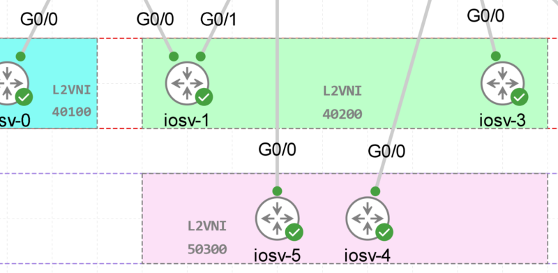
- Topology:
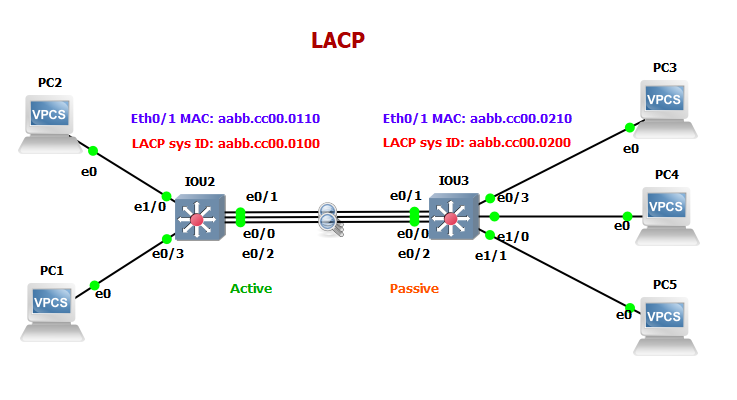
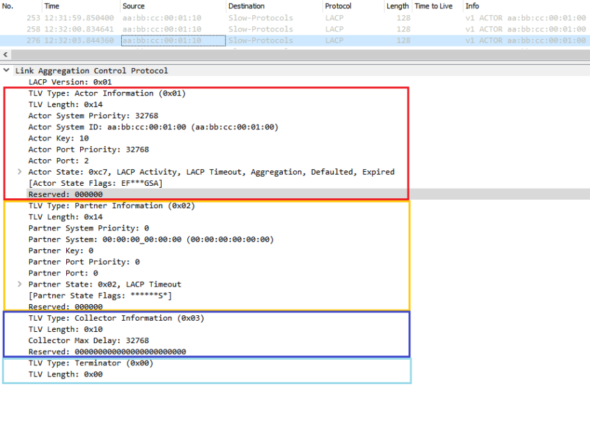
1- First, We enabled LACP active on the IOU2 switch interface (eth0/1-2), we have captured LACP packets:
- Source: aabb.cc00.0110
- Destination: 01:80:C2:00:00:02
- LACP Actor: Referring to the port sending the LACP packet. In the LACPDU, we see the Actor Information (Sys-id, port priority) with no Partner Information, which means no LACPDU is received yet from the partner.
- Actor Key = 10, this indicates the port channel configured ID ( in our case 10)
- Actor port = 2, this represents the number of the sender’s physical port within the port channel.
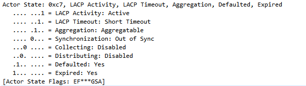
- Actor State = 0xc7 (indicates that the actor is LACP Active, each bit represents a flag or parameters of the Actor)
- Collector in LACP refers to the device collecting the frames to be load balanced or distributed over the port channel”.
- Terminator in LACP refers to the device receiving the frames that were load balanced over the port channel”.
2- Second, we enabled the interfaces on the IOU3 switch interfaces:
In the Wireshark capture, we see the LACP packet from the IOU3
- The actor represents the sending interface on the IOU3 switch (Actor information TLV including Actor system ID and priority, Actor port and priority & Actor state)
- Actor state:
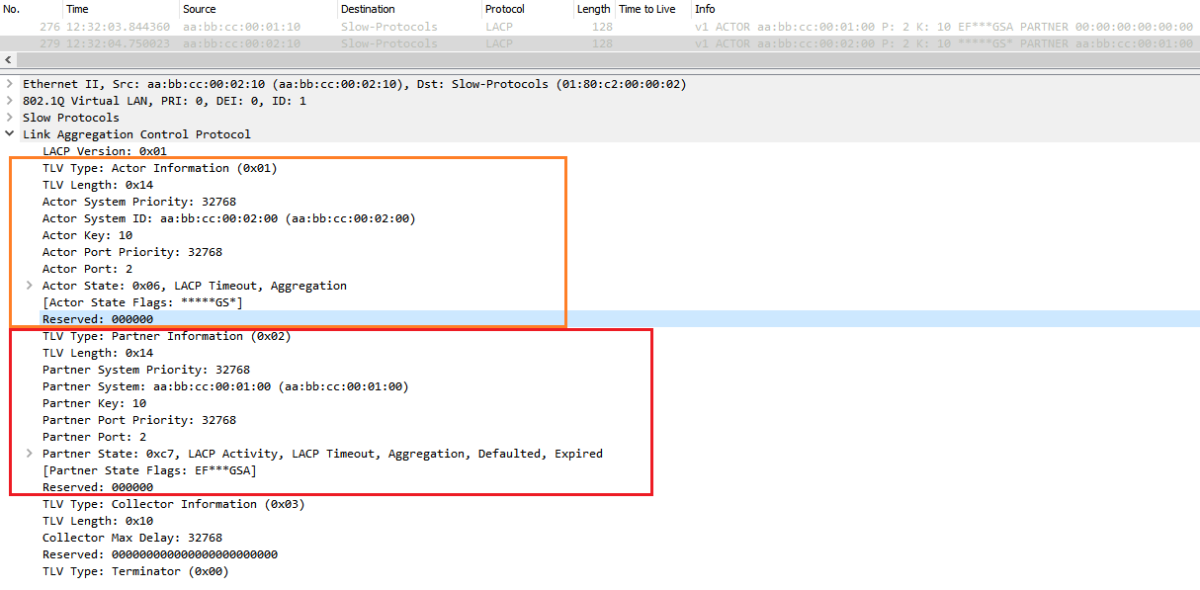
After the exchange of LACPDUs, the actor and the partner should have agreed on each other’s status and verified that each has correctly recognized the other’s status (by checking the values that the other device is sending in the ‘partner’ fields of the LACPDUs).
Once the actor and partner have come to an agreement about each other’s settings, the devices can make a decision about whether the ports at each end of the link can be added to an aggregation.
LACP Key:
When we enable LACP, it will send LACPDUs down each ‘Active mode’ connected link to find any partners that also have LACP enabled. If a reply is received, the device builds up a database of which link goes to which partner device. When LACP detects that two or more links are connected to the same partner device, and have the same ‘key’, it will aggregate them into one logical link.
Any further physical links added to the same partner system will simply be added to the now-existing trunk group (within physical bounds). The same actions will take place if a port is in passive mode and it receives an LACP control packet – it will build a database of connected partners and begin sending control packets out that interface.
LACP automatically configures an administrative key value equal to the channel group identification number on each port configured to use LACP. The administrative key defines the ability of a port to aggregate with other ports. A port’s ability to aggregate with other ports is determined by these factors:
- Port physical characteristics, such as data rate, duplex capability, and point-to-point or a shared medium
- Configuration restrictions that you establish
When 2 or more ports with the same key are configured, an LACP Etherchannel is establishe
Actor and Partner State Flags:
Let’s deep dive in the Actor and Partner States during the Negotiation process:
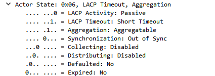
- Activity: It is set to indicate LACP active mode, cleared to indicate passive mode
- Timeout: It is set to indicate the device is requesting a fast (1s) transmit interval of its partner, cleared to indicate that a slow (30s) transmit interval is being requested.
- Aggregation: It is set to indicate that the port is configured for aggregation (typically always set)
- Synchronization: It is set to indicate that the system is ready and willing to use this link in the bundle to carry traffic. Cleared to indicate the link is not usable or is in standby mode.
- Collecting: It is set to indicate that traffic received on this interface will be processed by the device. Cleared otherwise.
- Distributing: It is set to indicate that the device is using this link transmit traffic. Cleared otherwise.
- Expired: It is set to indicate that no LACPDUs have been received by the device during the past 3 intervals. Cleared when at least one LACPDU has been received within the past three intervals.
- Defaulted: It is set to indicate that no LACPDUs have been received during the past 6 intervals. Cleared when at least one LACPDU has been received within the past 6 intervals. Once the defaulted flag transitions to set, any stored partner information is flushed.
The three main flags during the negotiation process are:
- Synchronization
- Collecting
- Distributing
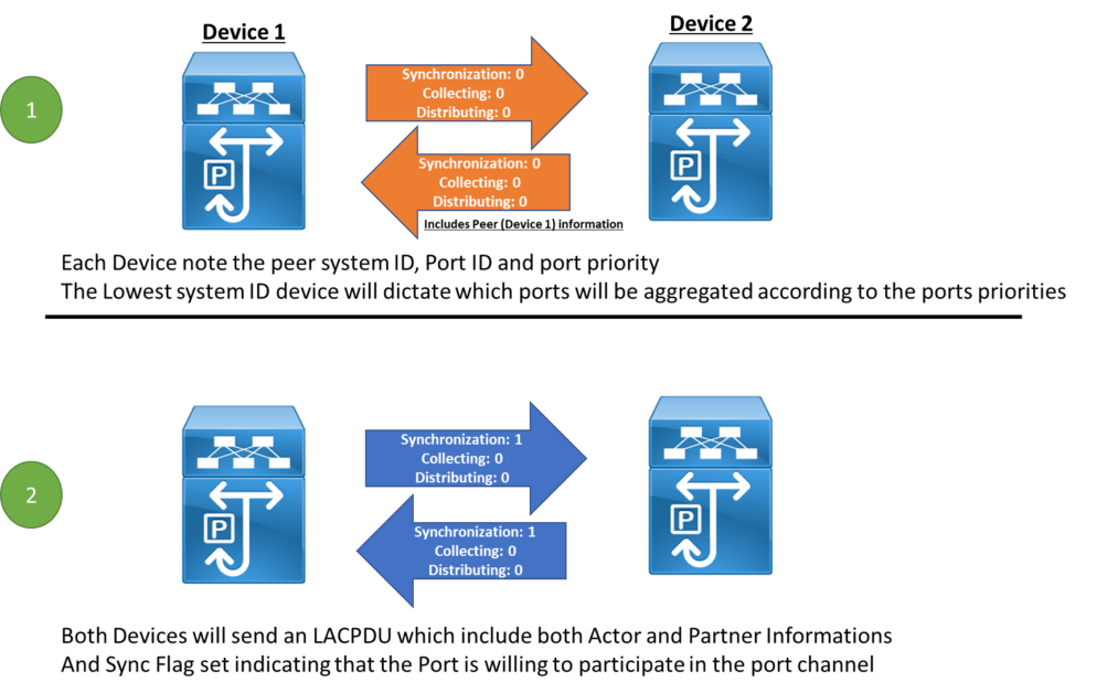
Step-1: Both Devices send LACPDU their first LACPDU (Assuming both are configured in Active mode):
- Synchronization: 0
Out of Sync, this bit set to 0 and it indicates that the remote port is not synchronized yet. - Collecting: 0
Disabled, this bit set to 0 and it indicates that the remote port is not operational and not ready to collect traffic over the port channel. - Distributing: 0
Disabled, this bit set to 0 and it indicates that the remote port is not operational and not ready to distribute traffic on the port channel.
Note: Device 2 send an LACPDU with sync 0, but, it include Device 1 (it’ peer) information in the LACPDU.
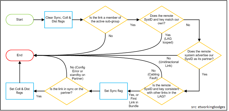
Step-2: Synchronization
Once the both devices receives the LACPDU from each other, they will collect the peer system ID and port ID and other Peer LACP Information from the received LACPDU (Step1).
Each Device know its peer priority and System ID, so, the device with lowest system ID will dictates the Ports that will join the port channel according to port priorities.
Since, Device-2 sent an LACPDU with Device-1 information included in it (Step1) & Device-1 verified that the other links part of the port-channel have the same Remote System and Key as the ones received on the Port (pass if it’s the only port in the port-channel).
Then, Device-1 will send an LACPDU that include local and peer Information with State flag Synchronization: 1
The same, Device-2 also will receive an LACPDU and see its information inside the received LACPDU, then check System ID and Key consistency and send an LACPDU with Flag In Sync.
This can summarized in the following picture:
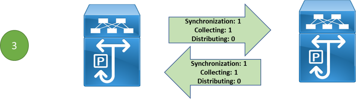
Step-3: Collecting
Once the Port on the Remote Peer is in Sync, (Flag set), the local device will send an LACP with Collecting Flag set indicating that the Device is ready to receive traffic on its Port (Interface).
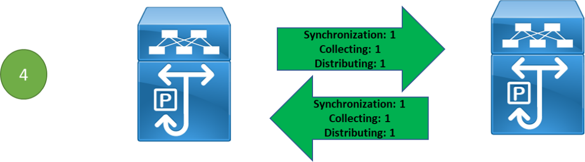
Step-3: Distributing
The Device Device will send LACPDU with the Distributing flag set to indicate they are transmitting Data traffic on the Port.
LACP modes
- Active: Enables LACP unconditionally.
- Passive: Enables LACP only when an LACP device is detected. (This is the default state)
note: Interfaces part of the passive LACP channel will act as access ports when they don’t receive any LACPDU.
Port channel Establishment | Active | Passive | On |
Active | Yes | Yes | No |
Passive | Yes | No | No |
On | No | No | Yes |
LACP Configuration
- LACP Layer2:
interface Port-channel10
 switchport
!
interface Ethernet0/0
 channel-group 10 mode active
!
interface Ethernet0/1
 channel-group 10 mode active
!
interface Ethernet0/2
channel-group 10 mode active- Verification:
IOU2#show etherchannel summary
Flags:  D - down        P - bundled in port-channel
        I - stand-alone s - suspended
        H - Hot-standby (LACP only)
        R - Layer3      S - Layer2
        U - in use      N - not in use, no aggregation
        f - failed to allocate aggregator

        M - not in use, no aggregation due to minimum links not met
        m - not in use, port not aggregated due to minimum links not met
        u - unsuitable for bundling
        d - default port

        w - waiting to be aggregated
Number of channel-groups in use: 1
Number of aggregators:           1

Group  Port-channel  Protocol    Ports
------+-------------+-----------+-----------------------------------------------
10     Po10(SU)        LACP      Et0/0(P)       Et0/1(P)       Et0/2(P)
Port-channel: Po10    (Primary Aggregator)

------------

Age of the Port-channel   = 0d:03h:33m:35s
Logical slot/port   = 16/1          Number of ports = 3
HotStandBy port = null
Port state          = Port-channel Ag-Inuse
Protocol            =   LACP
Port security       = Disabled
Fast-switchover     = disabled
Load share deferral = disabled

Ports in the Port-channel:

Index   Load      Port          EC state       No of bits
------+------+------------+------------------+-----------
 0      00          Et0/0             Active   0
 0      00          Et0/1             Active   0
 0      00          Et0/2             Active   0

Time since last port bundled:    0d:00h:04m:23s    Et0/1
Time since last port Un-bundled: 0d:01h:03m:58s    Et0/0
Cisco LACP Fast
In the LACP standard, LACP packets are sent out every 30 seconds, if no LACP packet is received for 3 intervals (90 sec) then the interface will be removed from the port channel.
With LACP Fast, the interval is reduced to 1 second, which means, if there’s no LACP packet received within 3 seconds, then the link will be removed from the port channel.
- LACP Fast configuration:
Switch(config)# interface Gig0/0
Switch(config-if-range)# lacp rate fast
To turn it back to the standard timers:
Switch1(config)# interface range Gig0/0-1
Switch1(config-if-range)# lacp rate slow
LACP Load Balancing
The standard mode of load balancing packets across LACP EtherChannel is per-flow so each flow will always get one of the EtherChannel links to get to the peer. In simple words, Each flow will get its own port from EtherChannel links and only get the port max speed.
This mechanism uses the hash algorithm to calculate the address in a data frame and generate a hash key based on which the switch will select a link within the EtherChannel to forward the traffic flow.
Each MAC or IP address corresponds to a hash key, so the system uses different outbound interfaces to forward data. This mechanism ensures that frames of the same data flow are forwarded on the same physical link and implements load balancing of data flows.
- How to choose the best (appropriate) Load-balancing algorithm:
You can set the load balancing mode based on traffic models. When a parameter of traffic changes frequently, you can set the load-balancing mode based on this parameter to ensure that the traffic is load balanced evenly, for example,
- If IP addresses in packets change frequently, use the load balancing mode based on dst-ip, src-ip, or src-dst-ip so that traffic can be properly load-balanced among physical links.
- If MAC addresses in packets change frequently and IP addresses are fixed, use the load balancing mode based on dst-mac, src-mac, or src-dst-mac so that traffic can be properly load-balanced among physical links.
- LACP load-balancing configuration example:
To check the actual LACP Load-Balancing algorithm on the cisco switch:
IOU2#show etherchannel load-balance
EtherChannel Load-Balancing Configuration:
        src-dst-ip

EtherChannel Load-Balancing Addresses Used Per-Protocol:
Non-IP: Source XOR Destination MAC address
  IPv4: Source XOR Destination IP address
  IPv6: Source XOR Destination IP address
- Change the load-balance method:
IOU2#conf t
Enter configuration commands, one per line.  End with CNTL/Z.
IOU2(config)#port-channel load-balance ?
  dst-ip       Dst IP Addr
  dst-mac      Dst Mac Addr
  src-dst-ip   Src XOR Dst IP Addr
  src-dst-mac  Src XOR Dst Mac Addr
  src-ip       Src IP Addr
  src-mac      Src Mac Addr

IOU2(config)#port-channel load-balance src-ip![Explore The BGP Path Selection Attributes [Explained with Labs]](https://learnduty.com/wp-content/uploads/2022/07/image-28-800x450.png)