IP Multicast – Understanding PIM-Bidir [Basic Configuration and Packet Flow]
Contents
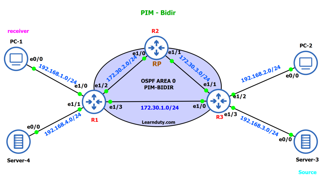
Topology
Initial IGP Configuration and verifications
Router R1:
interface Ethernet1/0
 ip address 192.168.1.254 255.255.255.0
 ip ospf 1 area 0
 duplex full
!
interface Ethernet1/1
 ip address 192.168.4.254 255.255.255.0
 ip ospf 1 area 0
 duplex full
!
interface Ethernet1/2
 ip address 172.30.2.1 255.255.255.0
 ip ospf 1 area 0
 duplex full
!
interface Ethernet1/3
 ip address 172.30.1.1 255.255.255.0
 ip ospf 1 area 0
 duplex full
!
router ospf 1

---------------

R1#show ip route

Gateway of last resort is not set

      2.0.0.0/32 is subnetted, 1 subnets
O        2.2.2.2 [110/11] via 172.30.2.2, 00:00:01, Ethernet1/2
      172.30.0.0/16 is variably subnetted, 5 subnets, 2 masks
C        172.30.1.0/24 is directly connected, Ethernet1/3
L        172.30.1.1/32 is directly connected, Ethernet1/3
C        172.30.2.0/24 is directly connected, Ethernet1/2
L        172.30.2.1/32 is directly connected, Ethernet1/2
O        172.30.3.0/24 [110/20] via 172.30.2.2, 00:17:58, Ethernet1/2
                       [110/20] via 172.30.1.2, 00:16:58, Ethernet1/3
      192.168.1.0/24 is variably subnetted, 2 subnets, 2 masks
C        192.168.1.0/24 is directly connected, Ethernet1/0
L        192.168.1.254/32 is directly connected, Ethernet1/0
O     192.168.2.0/24 [110/20] via 172.30.1.2, 00:09:21, Ethernet1/3
O     192.168.3.0/24 [110/20] via 172.30.1.2, 00:07:08, Ethernet1/3
      192.168.4.0/24 is variably subnetted, 2 subnets, 2 masks
C        192.168.4.0/24 is directly connected, Ethernet1/1
L        192.168.4.254/32 is directly connected, Ethernet1/1
Router R2:
Loopback 0 will be used as the Rendez point address on R2.
interface Loopback0
 ip address 2.2.2.2 255.255.255.255
 ip ospf 1 area 0
!
interface Ethernet1/0
 ip address 172.30.2.2 255.255.255.0
 ip ospf 1 area 0
 duplex full
!
interface Ethernet1/1
 ip address 172.30.3.1 255.255.255.0
 ip ospf 1 area 0
 duplex full
!
router ospf 1

-----------------

R2#show ip route

Gateway of last resort is not set

      2.0.0.0/32 is subnetted, 1 subnets
C        2.2.2.2 is directly connected, Loopback0
      172.30.0.0/16 is variably subnetted, 5 subnets, 2 masks
O        172.30.1.0/24 [110/20] via 172.30.3.2, 00:18:00, Ethernet1/1
                       [110/20] via 172.30.2.1, 00:19:22, Ethernet1/0
C        172.30.2.0/24 is directly connected, Ethernet1/0
L        172.30.2.2/32 is directly connected, Ethernet1/0
C        172.30.3.0/24 is directly connected, Ethernet1/1
L        172.30.3.1/32 is directly connected, Ethernet1/1
O     192.168.1.0/24 [110/20] via 172.30.2.1, 00:12:28, Ethernet1/0
O     192.168.2.0/24 [110/20] via 172.30.3.2, 00:10:21, Ethernet1/1
O     192.168.3.0/24 [110/20] via 172.30.3.2, 00:08:09, Ethernet1/1
O     192.168.4.0/24 [110/20] via 172.30.2.1, 00:11:56, Ethernet1/0
Router R3:
interface Ethernet1/0
 ip address 172.30.1.2 255.255.255.0
 ip ospf 1 area 0
 duplex full
!
interface Ethernet1/1
 ip address 172.30.3.2 255.255.255.0
 ip ospf 1 area 0
 duplex full
!
interface Ethernet1/2
 ip address 192.168.2.254 255.255.255.0
 ip ospf 1 area 0
 duplex full
!
interface Ethernet1/3
 ip address 192.168.3.254 255.255.255.0
 ip ospf 1 area 0
 duplex full
!
router ospf 1

--------------------

R3#show ip route

Gateway of last resort is not set

      2.0.0.0/32 is subnetted, 1 subnets
O        2.2.2.2 [110/11] via 172.30.3.1, 00:02:10, Ethernet1/1
      172.30.0.0/16 is variably subnetted, 5 subnets, 2 masks
C        172.30.1.0/24 is directly connected, Ethernet1/0
L        172.30.1.2/32 is directly connected, Ethernet1/0
O        172.30.2.0/24 [110/20] via 172.30.3.1, 00:19:03, Ethernet1/1
                       [110/20] via 172.30.1.1, 00:19:29, Ethernet1/0
C        172.30.3.0/24 is directly connected, Ethernet1/1
L        172.30.3.2/32 is directly connected, Ethernet1/1
O     192.168.1.0/24 [110/20] via 172.30.1.1, 00:13:31, Ethernet1/0
      192.168.2.0/24 is variably subnetted, 2 subnets, 2 masks
C        192.168.2.0/24 is directly connected, Ethernet1/2
L        192.168.2.254/32 is directly connected, Ethernet1/2
      192.168.3.0/24 is variably subnetted, 2 subnets, 2 masks
C        192.168.3.0/24 is directly connected, Ethernet1/3
L        192.168.3.254/32 is directly connected, Ethernet1/3
O     192.168.4.0/24 [110/20] via 172.30.1.1, 00:12:59, Ethernet1/0
PIM Bidir Configuration
1- Enable IP multicast routing and configure PIM-SM on All Interfaces on the routers R1, R2, R3:
- Router R1:
R1(config)#ip multicast-routing
R1(config)#int range e1/0-3
R1(config-if-range)#ip pim sparse-mode

R1#show ip pim neighbor
PIM Neighbor Table
Mode: B - Bidir Capable, DR - Designated Router, N - Default DR Priority,
      P - Proxy Capable, S - State Refresh Capable, G - GenID Capable
Neighbor          Interface                Uptime/Expires    Ver   DR
Address                                                            Prio/Mode
172.30.2.2        Ethernet1/2              00:01:18/00:01:25 v2    1 / DR S P G
172.30.1.2 Ethernet1/3 00:00:59/00:01:43 v2 1 / DR S P G- Router R2:
R1(config)#ip multicast-routing
R2(config)#int range e1/0-1
R2(config-if-range)#ip pim sparse-mode


R2#show ip pim neighbor
PIM Neighbor Table
Mode: B - Bidir Capable, DR - Designated Router, N - Default DR Priority,
      P - Proxy Capable, S - State Refresh Capable, G - GenID Capable
Neighbor          Interface                Uptime/Expires    Ver   DR
Address                                                            Prio/Mode
172.30.2.1        Ethernet1/0              00:02:32/00:01:38 v2    1 / S P G
172.30.3.2 Ethernet1/1 00:02:13/00:01:27 v2 1 / DR S P G- Router R3:
R1(config)#ip multicast-routing
R3(config)#int range e1/0-3
R3(config-if-range)#ip pim sparse-mode


R3#show ip pim neighbor
PIM Neighbor Table
Mode: B - Bidir Capable, DR - Designated Router, N - Default DR Priority,
      P - Proxy Capable, S - State Refresh Capable, G - GenID Capable
Neighbor          Interface                Uptime/Expires    Ver   DR
Address                                                            Prio/Mode
172.30.1.1        Ethernet1/0              00:02:56/00:01:17 v2    1 / S P G
172.30.3.1        Ethernet1/1              00:02:56/00:01:19 v2    1 / S P G
2- Enable PIM Bidir and configure RP on all routers:
ip pim bidir-enable
ip pim rp-address 2.2.2.2 bidir
no ip pim autorp
3- Configure R2 to be the static RP:
interface Loopback0
 ip address 2.2.2.2 255.255.255.255
 ip pim sparse-mode
 ip ospf 1 area 0
Verification and PIM-Bidir Packet Flow
We have set up an example where PC-1 is the receiver:
- R1 configuration:
interface Ethernet1/0
 ip address 192.168.1.254 255.255.255.0
 ip pim sparse-mode
 ip ospf 1 area 0
duplex full- verification:
R1#show ip igmp groups
IGMP Connected Group Membership
Group Address Interface Uptime Expires Last Reporter Group Accounted
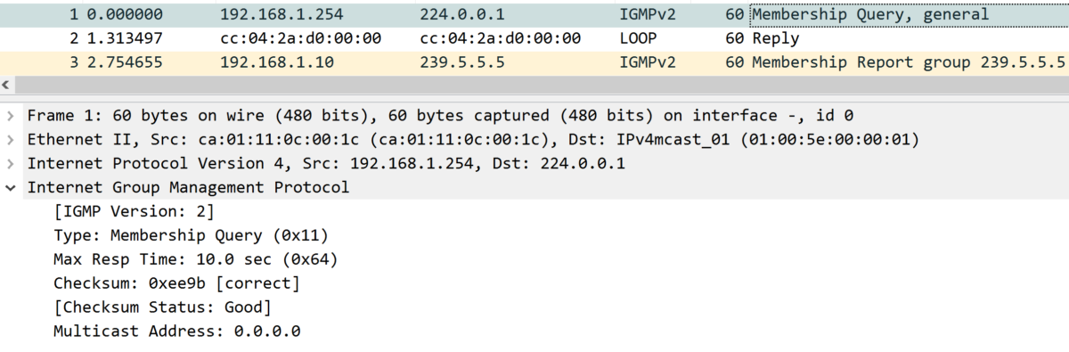
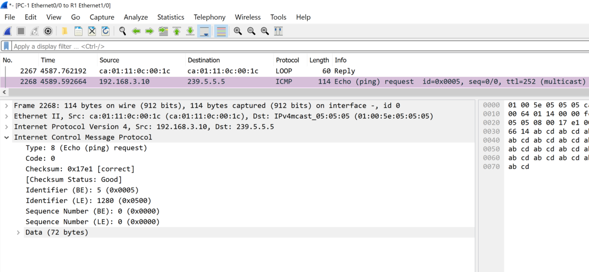
239.5.5.5 Ethernet1/0 00:14:43 00:02:21 192.168.1.10In the Wireshark capture on the link between PC-1 and R1, we see that the Router R1 is sending IGMPv2 Membership Query and PC-1 responding with IGMPv2 Membership Report indicating its interest to join the Group 239.5.5.5 and to receive traffic from it.
Please note that there no multicast traffic sent from the source yet.
IGMP General query membership from R1:
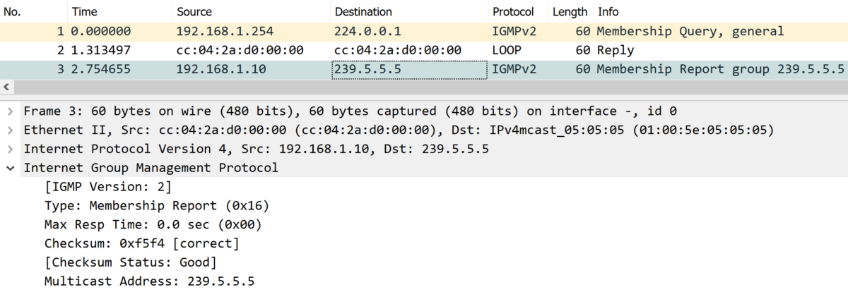
IGMP Membership Report from the receiver PC-1 for the group 239.5.5.5:
- R1 IP mroute:
R1#show ip mroute

(*,224.0.0.0/4), 00:16:53/-, RP 2.2.2.2, flags: B
  Bidir-Upstream: Ethernet1/2, RPF nbr: 172.30.2.2
  Incoming interface list:
    Ethernet1/1, Accepting/Sparse
    Ethernet1/0, Accepting/Sparse
    Ethernet1/2, Accepting/Sparse

(*, 239.5.5.5), 00:17:41/00:02:20, RP 2.2.2.2, flags: BC
  Bidir-Upstream: Ethernet1/2, RPF nbr 172.30.2.2
  Outgoing interface list:
    Ethernet1/0, Forward/Sparse, 00:16:52/00:02:20
    Ethernet1/2, Bidir-Upstream/Sparse, 00:16:53/stopped
On the IGMP Report membership is received by R1, it will add a new entry to its multicast routing table with outgoing interfaces:
– To the receiver (Ethernet1/0)
– To the RP (Ethernet 1/2) as Upstream, since we are using PIM Bidir.
The RPF interface is the interface toward an RP, and an RPF neighbor is the address of the next hop to the RP. It this example interface eth1/2 toward the RP.
The router is accepting multicast traffic for the whole 224.0.0.0/4 The incoming interfaces are:
- Eth1/2: picked from IGP as best path to the RP
- other interface Where PIM or IGMP is enabled expect the PIM neighbor to R3, because all multicast traffic must go through the RP in PIM Bidir (and link to R3 is not the best path IGP to the RP).
PIM Bidir Packet flow:
We started a ping from server-3 to 239.5.5.5 in order to simulate a multicast source:
Server-3#ping  239.5.5.5 repeat 100

Sending 110, 100-byte ICMP Echos to 239.5.5.5, timeout is 2 seconds:
Reply to request 0 from 192.168.1.10, 100 ms
Reply to request 1 from 192.168.1.10, 120 ms
Reply to request 2 from 192.168.1.10, 120 ms
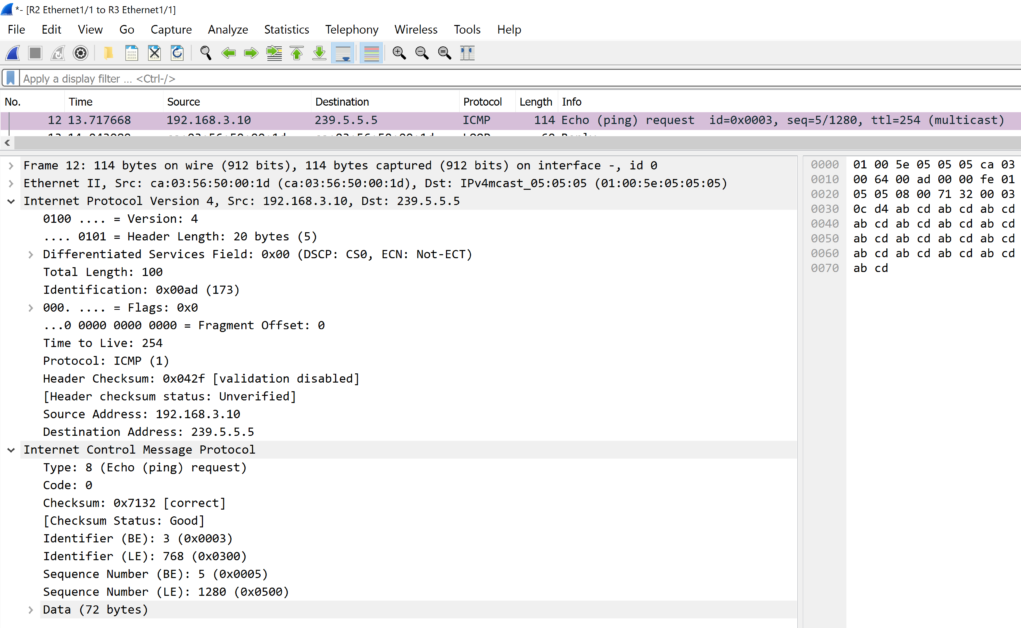
Packet capture between Server-3 and R3:
If we check the ip multicast routing table in R3, it is really simple, just a shared tree toward the RP for all multicast traffic, since, R3 doesn’t have a receiver for the group 239.5.5.5, no outgoing interface exist toward potential receivers.
R3#show ip mroute
(*,224.0.0.0/4), 00:32:25/-, RP 2.2.2.2, flags: B
  Bidir-Upstream: Ethernet1/1, RPF nbr: 172.30.3.1
  Incoming interface list:
    Ethernet1/0, Accepting/Sparse
    Ethernet1/2, Accepting/Sparse
    Ethernet1/3, Accepting/Sparse
    Ethernet1/1, Accepting/Sparse
So, basically R3, have a static RP configured 2.2.2.2, so once multicast traffic is received on one of the incoming interface (from server-3 on Eth1/3 in our lab) , Router R3 will check its IGP unicast routing table and finds out that the best path toward the RP is via the interface 1/1 and next next hop 172.30.3.1.
The multicast routing table will leverage the Bidir-Upstream entry and the multicast traffic is forwarded toward the RP (regardless the presence of receivers or not):
At this point the traffic is received by the RP, let’s check the IP multicast routing table on R2 (the RP):
R2#show ip mroute

(*,224.0.0.0/4), 00:51:26/-, RP 2.2.2.2, flags: B
  Bidir-Upstream: Loopback0, RPF nbr: 2.2.2.2
  Incoming interface list:
    Ethernet1/1, Accepting/Sparse
    Ethernet1/0, Accepting/Sparse
    Loopback0, Accepting/Sparse

(*, 239.5.5.5), 00:50:36/00:02:52, RP 2.2.2.2, flags: B
  Bidir-Upstream: Null, RPF nbr 0.0.0.0
  Outgoing interface list:
    Ethernet1/0, Forward/Sparse, 00:50:36/00:02:52
The RP is accepting multicast traffic from its PIM neighbors: R3 (eth1/1) and also R1 (eth1/0).
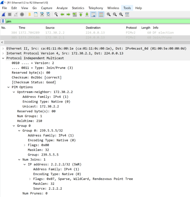
We see that the RP have an entry in the multicast table for the group 239.5.5.5 with an outgoing interface toward R1, but, how did the RP learned about it?
The answer is basically once R1 have sent an IGMP Membership query and the receiver PC-1 responded with IGMP Membership Report for the group 239.5.5.5, R1 sent a PIM join message toward the RP indicating that he have a receiver for the specific group. therefore, the RP installs a shared tree for the group in the multicast routing table and adds the interface toward R1 as outgoing interface.
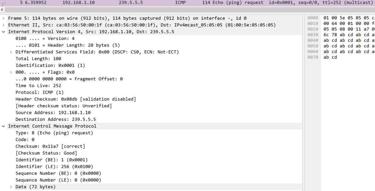
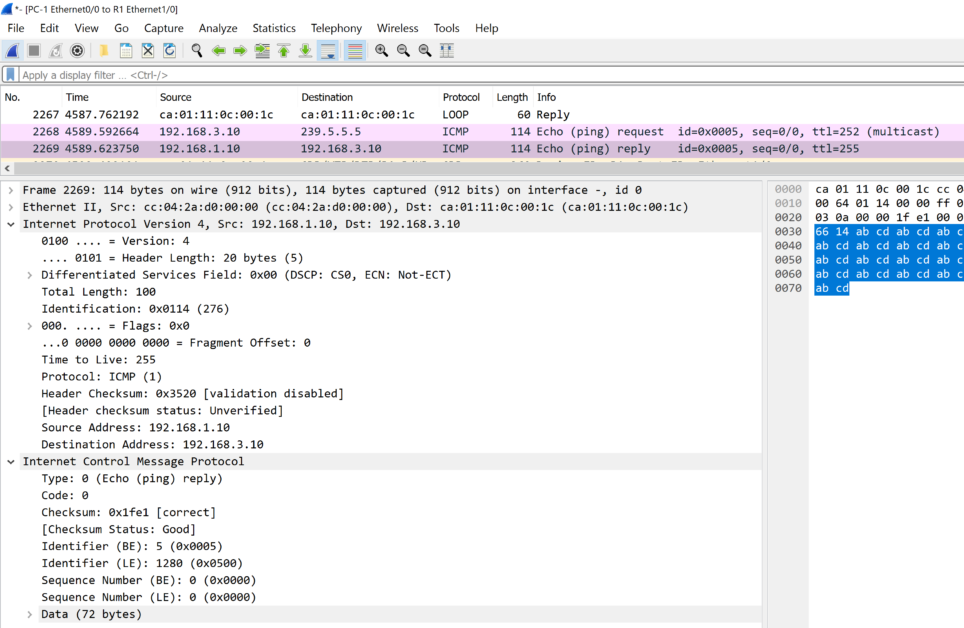
At this stage, the RP will sent the multicast traffic (ICMP request in our example) toward R1, once received, R1 will just check the IGMP group table to decide where to forward the multicast traffic for the group 239.5.5.5 and find that it have a receiver for the group (PC-1) and sent a copy of the traffic toward the receiver (multiple replicated copies are sent in case of multiple receivers are interested by the multicast traffic for the group)
Notice that the Upstream entry in PIM-Bidir is always toward the RP to allow the multicast traffic to flow in both direction via the RP:
- From the source toward the receiver, the upstream in R3 is pointing to the RP.
- From the receiver to the source (if role swapped), also, there an upstream entry to the RP.
R1#sh ip mroute

(*,224.0.0.0/4), 00:01:58/-, RP 2.2.2.2, flags: B
  Bidir-Upstream: Ethernet1/2, RPF nbr: 172.30.2.2
  Incoming interface list:
    Ethernet1/2, Accepting/Sparse
    Ethernet1/1, Accepting/Sparse
    Ethernet1/0, Accepting/Sparse

(*, 239.5.5.5), 00:02:52/00:02:07, RP 2.2.2.2, flags: BC
  Bidir-Upstream: Ethernet1/2, RPF nbr 172.30.2.2
  Outgoing interface list:
    Ethernet1/2, Bidir-Upstream/Sparse, 00:01:58/stopped
    Ethernet1/0, Forward/Sparse, 00:02:08/00:02:07
Note: the return traffic (if exist) is not multicast traffic, it is unicast from receiver to the source and could have different path than the ingress traffic (not through the RP).
![Explore The BGP Path Selection Attributes [Explained with Labs]](https://learnduty.com/wp-content/uploads/2022/07/image-28-800x450.png)