IP Multicast PIM Sparse Mode Configuration
Contents
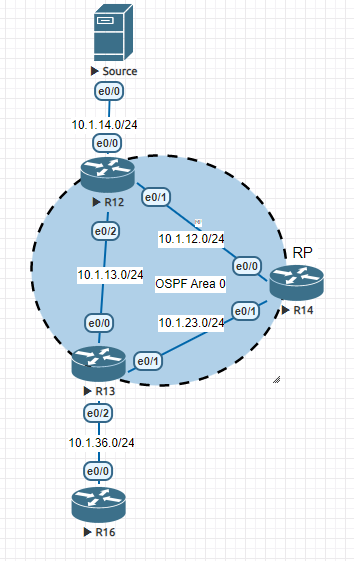
Topology
Note: this Lab is based on some PNETLab resources.
Initial Configuration
R12:
---
interface Ethernet0/0
no shutdown
ip address 10.1.14.1 255.255.255.0
ip ospf 1 area 0

interface Ethernet0/1
no shutdown
ip address 10.1.12.1 255.255.255.0
ip ospf 1 area 0
!
interface Ethernet0/2
no shutdown
ip address 10.1.13.1 255.255.255.0
ip ospf 1 area 0

router ospf 1


R14 (RP):
---
interface Ethernet0/0
no shutdown
ip address 10.1.12.2 255.255.255.0
ip ospf 1 area 0

interface Ethernet0/1
no shutdown
ip address 10.1.23.2 255.255.255.0
ip ospf 1 area 0
!
interface Loopback0
 ip address 2.2.2.2 255.255.255.255
 ip ospf 1 area 0

router ospf 1

R13:
---
interface Ethernet0/0
no shutdown
ip address 10.1.13.3 255.255.255.0
ip ospf 1 area 0
!
interface Ethernet0/1
no shutdown
ip address 10.1.23.3 255.255.255.0
ip ospf 1 area 0
!
interface Ethernet0/2
no shutdown
ip address 10.1.36.3 255.255.255.0
ip ospf 1 area 0

router ospf 1
PIM SM Configuration
On all routers:
- Activate multicast routing
- enable PIM Sparse mode under the interfaces (between routers to form PIM neighborship and also the interfaces facing the hosts to query IGMP)
- Disable PIM Auto-RP which is enabled by default, we will use static RP.
ip multicast-routing

interface Ethernet0/0
 ip pim sparse-mode
!
interface Ethernet0/1
 ip pim sparse-mode
!
interface Ethernet0/2
 ip pim sparse-mode
!

ip pim rp-address 2.2.2.2
no ip pim autorp
Verifications
- R12 (source router):
R12#show ip pim neighbor
PIM Neighbor Table
Mode: B - Bidir Capable, DR - Designated Router, N - Default DR Priority,
      P - Proxy Capable, S - State Refresh Capable, G - GenID Capable
Neighbor          Interface                Uptime/Expires    Ver   DR
Address                                                            Prio/Mode
10.1.12.2         Ethernet0/1              1d12h/00:01:26    v2    1 / DR S P G
10.1.13.3         Ethernet0/2              00:00:49/00:01:24 v2    1 / DR S P G


R12#show ip mroute
IP Multicast Routing Table
Flags: D - Dense, S - Sparse, B - Bidir Group, s - SSM Group, C - Connected,
       L - Local, P - Pruned, R - RP-bit set, F - Register flag,
       T - SPT-bit set, J - Join SPT, M - MSDP created entry, E - Extranet,
       X - Proxy Join Timer Running, A - Candidate for MSDP Advertisement,
       U - URD, I - Received Source Specific Host Report,
       Z - Multicast Tunnel, z - MDT-data group sender,
       Y - Joined MDT-data group, y - Sending to MDT-data group,
       G - Received BGP C-Mroute, g - Sent BGP C-Mroute,
       N - Received BGP Shared-Tree Prune, n - BGP C-Mroute suppressed,
       Q - Received BGP S-A Route, q - Sent BGP S-A Route,
       V - RD & Vector, v - Vector, p - PIM Joins on route,
       x - VxLAN group
Outgoing interface flags: H - Hardware switched, A - Assert winner, p - PIM Join
 Timers: Uptime/Expires
 Interface state: Interface, Next-Hop or VCD, State/Mode

(*, 239.5.5.5), 00:00:28/stopped, RP 2.2.2.2, flags: SPF
  Incoming interface: Ethernet0/1, RPF nbr 10.1.12.2
  Outgoing interface list: Null

(10.1.14.4, 239.5.5.5), 00:00:28/00:02:31, flags: FT
  Incoming interface: Ethernet0/0, RPF nbr 0.0.0.0, Registering
  Outgoing interface list:
    Ethernet0/2, Forward/Sparse, 00:00:28/00:03:01
- R14 (RP router):
R14#show ip pim neighbor
PIM Neighbor Table
Mode: B - Bidir Capable, DR - Designated Router, N - Default DR Priority,
      P - Proxy Capable, S - State Refresh Capable, G - GenID Capable
Neighbor          Interface                Uptime/Expires    Ver   DR
Address                                                            Prio/Mode
10.1.12.1         Ethernet0/0              1d12h/00:01:22    v2    1 / S P G
10.1.23.3         Ethernet0/1              1d12h/00:01:17    v2    1 / DR S P G

R14#show ip mroute
IP Multicast Routing Table
Flags: D - Dense, S - Sparse, B - Bidir Group, s - SSM Group, C - Connected,
       L - Local, P - Pruned, R - RP-bit set, F - Register flag,
       T - SPT-bit set, J - Join SPT, M - MSDP created entry, E - Extranet,
       X - Proxy Join Timer Running, A - Candidate for MSDP Advertisement,
       U - URD, I - Received Source Specific Host Report,
       Z - Multicast Tunnel, z - MDT-data group sender,
       Y - Joined MDT-data group, y - Sending to MDT-data group,
       G - Received BGP C-Mroute, g - Sent BGP C-Mroute,
       N - Received BGP Shared-Tree Prune, n - BGP C-Mroute suppressed,
       Q - Received BGP S-A Route, q - Sent BGP S-A Route,
       V - RD & Vector, v - Vector, p - PIM Joins on route,
       x - VxLAN group
Outgoing interface flags: H - Hardware switched, A - Assert winner, p - PIM Join
 Timers: Uptime/Expires
 Interface state: Interface, Next-Hop or VCD, State/Mode

(*, 239.5.5.5), 12:54:17/00:03:18, RP 2.2.2.2, flags: S
  Incoming interface: Null, RPF nbr 0.0.0.0
  Outgoing interface list:
    Ethernet0/1, Forward/Sparse, 11:45:25/00:03:18

(10.1.14.4, 239.5.5.5), 00:02:01/00:01:38, flags: PT
  Incoming interface: Ethernet0/0, RPF nbr 10.1.12.1
Outgoing interface list: Null- R13 (receiver router):
R13#show ip pim neighbor
PIM Neighbor Table
Mode: B - Bidir Capable, DR - Designated Router, N - Default DR Priority,
      P - Proxy Capable, S - State Refresh Capable, G - GenID Capable
Neighbor          Interface                Uptime/Expires    Ver   DR
Address                                                            Prio/Mode
10.1.13.1         Ethernet0/0              00:03:28/00:01:42 v2    1 / S P G
10.1.23.2         Ethernet0/1              1d12h/00:01:36    v2    1 / S P G

R13#show ip mroute
IP Multicast Routing Table
Flags: D - Dense, S - Sparse, B - Bidir Group, s - SSM Group, C - Connected,
       L - Local, P - Pruned, R - RP-bit set, F - Register flag,
       T - SPT-bit set, J - Join SPT, M - MSDP created entry, E - Extranet,
       X - Proxy Join Timer Running, A - Candidate for MSDP Advertisement,
       U - URD, I - Received Source Specific Host Report,
       Z - Multicast Tunnel, z - MDT-data group sender,
       Y - Joined MDT-data group, y - Sending to MDT-data group,
       G - Received BGP C-Mroute, g - Sent BGP C-Mroute,
       N - Received BGP Shared-Tree Prune, n - BGP C-Mroute suppressed,
       Q - Received BGP S-A Route, q - Sent BGP S-A Route,
       V - RD & Vector, v - Vector, p - PIM Joins on route,
       x - VxLAN group
Outgoing interface flags: H - Hardware switched, A - Assert winner, p - PIM Join
 Timers: Uptime/Expires
 Interface state: Interface, Next-Hop or VCD, State/Mode

(*, 239.5.5.5), 12:55:23/stopped, RP 2.2.2.2, flags: SJC
  Incoming interface: Ethernet0/1, RPF nbr 10.1.23.2
  Outgoing interface list:
    Ethernet0/2, Forward/Sparse, 11:46:32/00:02:30

(10.1.14.4, 239.5.5.5), 00:03:07/00:02:52, flags: JT
  Incoming interface: Ethernet0/0, RPF nbr 10.1.13.1
  Outgoing interface list:
    Ethernet0/2, Forward/Sparse, 00:03:07/00:02:30
Multicast PIM Sparse Mode Packet flow
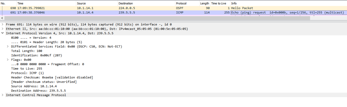
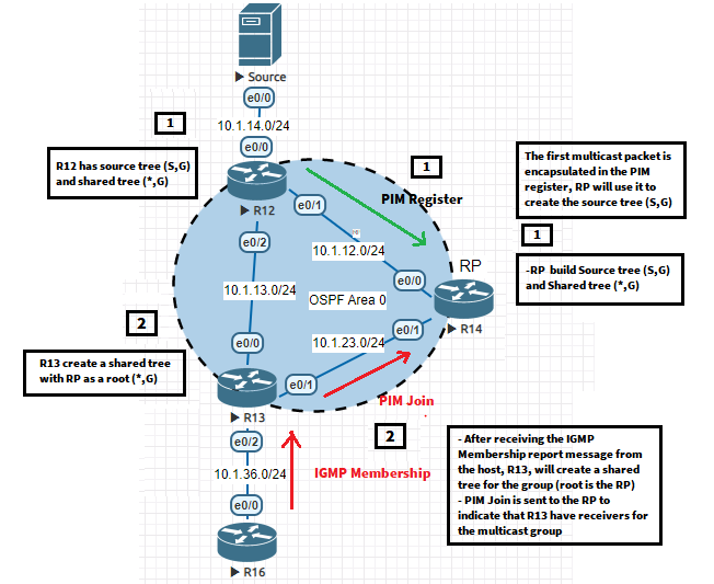
Step-1: The source PIM router (R12) receives the Multicast traffic packet from the source:
Step-2: The source PIM router (R12) encapsulates the received multicast packet inside a PIM Register message and sends it to the RP (2.2.2.2):
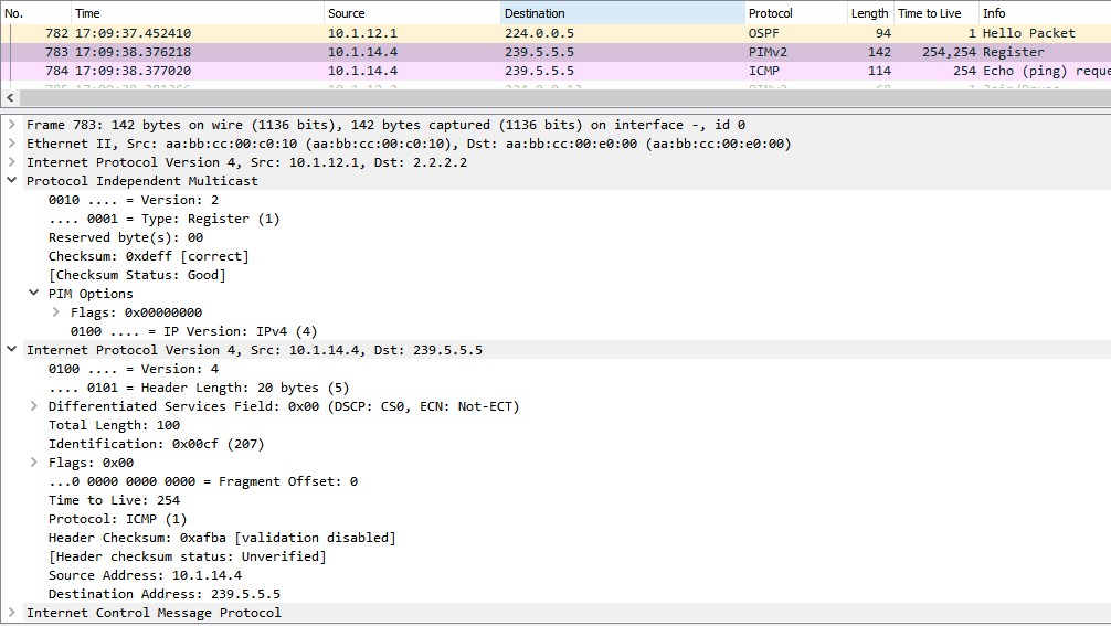
We can see that on the source router (R12), an Interface Tunnel0 (type PIM Encap) was created, It has source 10.1.12.1 (the exit interface toward 2.2.2.2 according to routing table, OSPF in our case) and the destination of the tunnel is RP (2.2.2.2).
R12#show ip pim tunnel
Tunnel0
  Type  : PIM Encap
  RP    : 2.2.2.2
  Source: 10.1.12.1
The purpose of this Tunnel is to encapsulate the original multicast packet from the source inside a PIM Register message (first packet).
The outer IP source is the R12 tunnel source (10.1.12.1) and the Outer IP destination is the RP).
Notes:
- The source router R12, will only send the first multicast packet encapsulated in a PIM Register to the RP.
- The PIM Register message allows the RP to:
– Have the source tree entry (S, G) which is used to receive (and send) multicast traffic for group G from the source S (the information about (S, G) is retrieved from the encapsulated original packet inside the PIM Register Message.
– Forwards the first packet via the shared tree (after Decap) to the receivers.
That’s the half of the story, On the RP side, in order to Decapsulate this PIM Register Message, the RP has two PIM Tunnel Interfaces:
- Tunnel1: used to Decapsulate the PIM Register message received from the source router.
- Tunnel0: it’s used in the case that the RP is also a source router for Multicast traffic.
R14#show ip pim tunnel
Tunnel0
  Type  : PIM Encap
  RP    : 2.2.2.2*
  Source: 10.1.12.2
Tunnel1*
  Type  : PIM Decap
  RP    : 2.2.2.2*
  Source: -
With the PIM register Message, the RP knows the source router and also the Multicast Group. The RP will create a source tree (S, G), in our case (10.1.14.4, 239.5.5.5).
Initially, In PIM Sparse Mode:
- The Multicast traffic from the source to the RP will use the source tree (S, G).
- The Multicast traffic from the RP to the receivers will use the shared tree (*, G) with RP as the root of the tree.
Step-3: When the RP receives the PIM register from the source, 2 scenarios can occur:
- If nobody is interested in receiving this Multicast traffic from this group, the PIM Register is rejected and the RP will send a PIM Register-Stop message to the source router (which timeout in 60 seconds).
After the timer expiration, the source router will send a PIM Register Null message: this message doesn’t encapsulate the multicast traffic from the source. If the RP has receivers for the multicast group, it will accept it, else, it will be rejected and another PIM Register stop gonna be sent to the source router. - If there is at least 1 receiver for the Multicast group (the multicast group is mentioned inside the PIM Register packet), the Register Message is accepted:
Once A receiver (host R16 in our case) sends an IGMP Membership Report for the group 239.5.5.5 to R13 (destination router), R13 will send a PIM Join message toward the RP (any router between the receiver router and RP will forward the Join message to the RP).
By the end of this, the RP will receive the Join message and create the Shared distribution tree for this Multicast group (RP is the root of this tree and decides for which receivers, it will forward the multicast traffic to the given Multicast group).
Notes: - The forwarding of the Join message from the receiver router to the RP is based on the unicast routing table (destination: RP @IP 2.2.2.2).
- The shared distribution tree is per Multicast group, Multiple Shared distribution trees can exist.
At this point, the first packet is encapsulated in a PIM Register message and sent to the RP via the source tree (S, G). the RP decapsulates the PIM register Packet and sends the original multicast packet to the receivers via the shared tree (*, G).
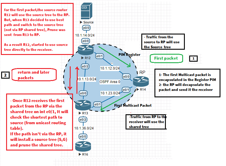
- Step-4: When R13 has received the first packet of multicast traffic from the source through the RP (via the shared tree (*, G), the receiver router has already learned the source address of this traffic.
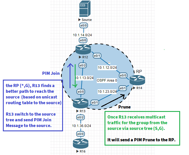
R13 (receiver router) will check the unicast routing table to the source, according to the SPT threshold value, it will decide to switch the source tree (directly to the source) instead of the shared tree (via RP) to receive this traffic. As a result, it will send PIM Join messages to the source.
Once R13 starts receiving traffic from the source via source (S, G), it will send a Prune message to the RP indicating, that it has already switched to the source tree and no more uses the shared tree via the RP.
![Explore The BGP Path Selection Attributes [Explained with Labs]](https://learnduty.com/wp-content/uploads/2022/07/image-28-800x450.png)