How Spanning Tree Protocol Works [ STP Deep Dive]
Contents
What is Spanning Tree
The Spanning Tree Protocol (STP) is a network protocol that builds a loop-free logical topology for Ethernet networks. The basic function of STP is to prevent bridge loops and the broadcast radiation that results from them. Spanning tree also allows a network design to include backup links providing fault tolerance if an active link fails.
As the name suggests, STP creates a spanning tree that characterizes the relationship of nodes within a network of connected layer-2 bridges and disables those links that are not part of the spanning tree, leaving a single active path between any two network nodes.
Invented by: Radia Perlman
Why do we need STP
The need for the Spanning Tree Protocol (STP) arose because switches in local area networks (LANs) are often interconnected using redundant links to improve resilience should one connection fail. However, this connection configuration creates a switching loop resulting in broadcast radiations and MAC table instability.
To avoid the problems associated with redundant links in a switched LAN, STP is implemented on switches to create a Loop-free Layer 2 network topology.
How Spanning Tree Protocol Works
When the switches first come up, they start the root Bridge selection process. Each switch transmits a BPDU to the directly connected switch on a per-VLAN basis.
As the BPDU goes out through the network, each switch compares the BPDU that the switch sends to the BPDU that the switch receives from the neighbors.
Initially, each switch sends BPDU containing the Root ID and Bridge ID with the same value as itself, assuming the Root ID role.
Then, Each switch compares its BBDU with the received BPDU and decides which switch is the Root bridge based on the Bridge ID (lower wins the election). When two connected switches compare their BPDU and decide which one is the root bridge, the non-root bridge will send BPDUs to other switches containing the root BPDU in the Root ID field.
Finally, All the switches agree on which switch is the root switch. The switch with the lowest bridge ID in the network wins this election process.
The Bridge ID = STP priority + System MAC
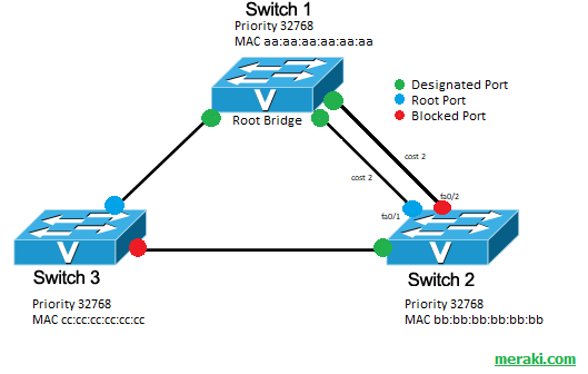
STP Port Roles
- Root: Ports on non-root switches with the best cost path to root bridge. These ports forward data to the root bridge. (All Root port are is FWD state)
- Designated: Ports on root and designated switches. All ports on the root bridge will be designated.
- Designated ports are in forwarding state
- Blocked: All other ports to bridges or switches are in a blocked state. Access ports going to workstations or PCs are not affected.
After the election of the Root Bridge, STP determines the role of each port in the topology which implicate their state:
STP Building Loop Free Topology process:
- All ports of the Root Bridge are Designated Ports (DP)
- On each switch, The port with the lowest root path cost (path to the Root Bridge) is selected as the Root Port (RP):
– If the path cost is the same, the switch will select the port with the lowest sender BID as the selected root port.
– If the sender BID is the same (usually the same switch), the port with the lowest physical port number on the sending switch will be selected as the root bridge (as the final tie-breaker). - Select the Designated Port for each segment (link that doesn’t include a Root Port):
– The Designated Port (DP) is Port belonging to the switch with the lowest Spanning Tree Path Cost to the Root Bridge, the other port in the segment is a Non-Designated-Port.
– If both switch in that segment have the same accumulated path cost to the Root Bridge, there is a tie breaker which is: The Designated Port is the port on the switch with lowest (better) Spanning Tree Bridge ID and the other port on the link as Non designated port. - The Root Port and Designated port are in Forwarding state and the rest of the ports are Blocked.
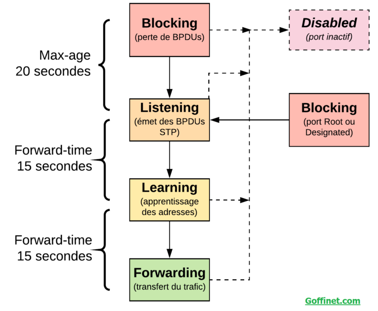
STP Port States
During the STP process, a port will pass through multiple states:
- Disabled: The result of an administrative command that will disable the port.
- Blocking: When a device is connected, the port will first enter the blocking state.
- Listening: The switch will listen for and send BPDUs.
- Learning: The switch will receive a superior BPDU, will stop sending its own BPDUs, and will relay the superior BPDUs.
- Forwarding: The port is forwarding traffic.
BDPU Frame
Bridge Protocol Data Units (BPDUs) are frames that contain information about the spanning tree protocol (STP). A switch sends BPDUs using a unique source MAC address from its origin port to a multicast address with destination MAC (01:80:C2:00:00:00, or 01:00:0C:CC:CC:CD for Cisco proprietary Per VLAN Spanning Tree).
By default, the BPDUs are sent every 2 seconds.
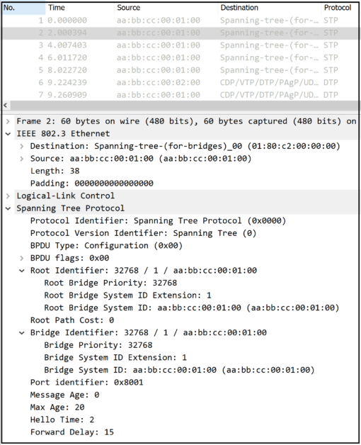
Let’s take a Look at the BPDU fields:
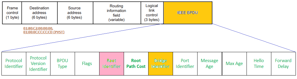
BPDU Fields:
- Message Type (1 byte): the frame can be a Configuration or TCN BPDU:
– TCN (Topology Change Notification): is sent by bridges towards the root bridge to notify changes in the topology, such as port up or port down (sent out of the Root Port in case of Topology change).
– Configuration BPDU (Hello): sent by the Root bridges to provide information to all switches.
- Flags (1 byte): differentiate between the TC (Topology Change) and TCA (Topology Change Notification Acknowledgement).
– A TCN BPDU has either the TC or TCA bit set.
- Root ID (8 bytes): represent the Root Bridge ID (2-byte priority + 6-byte MAC address).
- Root Path Cost (4 bytes): contains the sender’s cost to the root switch.
- Bridge ID (8 bytes): represents the BID of the sender (2-byte priority + 6-byte MAC address).
- Port ID (2 bytes): contains the sender’s port priority + port number from which the BPDU was sent.
- Message Age (2 bytes): represents the amount of time since the root sent the BPDU. Message Age is increased by one every time the BPDU is forwarded by a switch. BPDU sent by Root have Message age set to 0.
- Max Age (2 bytes): indicates when the current BPDU should be deleted. The BPDU received on a port expires after (Max Age – Message Age) seconds.
meaning, if the message age value reaches Max age, the BPDU is discarded.
- Hello Time (2 bytes): indicates how often BPDUs are sent.
- Forward Delay (2 bytes): indicates the time a switch should wait before transitioning to a new state after a topology change
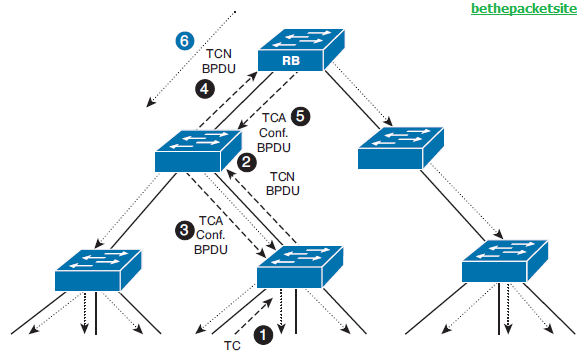
Topology Change Notification (TCN)
1- Change detected and TCN generated: When a switch detects a topology change it will generate a TCN BPDU, which is a special BPDU. This BPDU is sent on the root port. This BPDU must be acknowledged by the upstream switch until the TCN eventually reaches the root.
2- Root send out Configuration BPDU: After the TCN BPDU has reached the root bridge, the root bridge will send out configuration BPDU with TC bit set. The root does this for MaxAge + FWD_DELAY seconds which is 20 + 15 seconds by default, for a total of 35 seconds (The BPDU doesn’t contain info about what is the change in the topology, the Root bridge just indicate to all the switches under him that there is a change).
3- switches receive the Configuration BPDU with TC bit set: When the switches receive this BPDU with TC set, they will shorten the timeout of the MAC address table (MAC Aging timer) to flush out stale entries. The timeout is then set to 15 seconds, so stale entries will be removed but active flows will be relearned through the now active ports (Basically, the switches knows that there is a Topology change, so they will shorten the MAC learning timer to avoid any MAC that doesn’t really reside on their ports after the change).
Note: mean while, the Root still send the Helllo BPDU (configuration BPDU) each two sec by default in order for the STP Root to sustain the loop free tree (the non root bridge need the receive these frames unless after 20 sec (max age), they will consider the Root down and rebuild another spanning (the whole election process restarts)
Reference:
https://en.wikipedia.org/wiki/Spanning_Tree_Protocol
Cisco.com
Meraki.com
Goffinet.com
![Explore The BGP Path Selection Attributes [Explained with Labs]](https://learnduty.com/wp-content/uploads/2022/07/image-28-800x450.png)