Configure Policy Based routing (PBR) [step by step]
![Configure Policy Based routing (PBR) [step by step]](https://learnduty.com/wp-content/uploads/2021/07/word-image-128.png?v=1647900711)
Notes Before starting our lab on PBR:
- Standard routing protocols only check the destination of the packet (not the source..)
- Policy-Based routing overrides the existing routing protocol, the reason is that the PBR process intercepts the packet before the routing protocol.
Steps:
1- Configure Access-list for matching src IP, dst IP, or both (or matching specific protocol UDP/TCP by using extended ACL…)
2- Configure the route-map that will:
first Match the ACL ==> then set the action (Next hop ….)


3- Apply the Route-map on the incoming Interface
Let’s jump in and start configuring PBR.
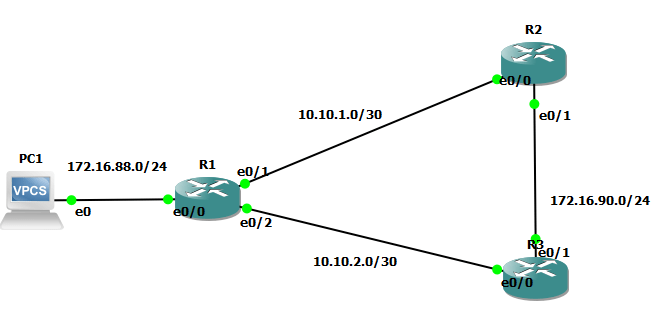
Topology:

Step 1: Connectivity and OSPF configuration:
Configure all the Interfaces and the OSPF routing on all Routers:
for our purpose, we will change the OSPF cost to R3 router to 16600 in order to prefer the route to R2
(later on in this Lab, we will use PBR to overide it):
- R1 configuration:
interface Ethernet0/0
ip address 172.16.88.1 255.255.255.0
ip policy route-map GOTO-R3
half-duplex
!
interface Ethernet0/1
ip address 10.10.1.1 255.255.255.252
ip ospf 100 area 0
half-duplex
!
interface Ethernet0/2
ip address 10.10.2.1 255.255.255.252
ip ospf cost 16600
ip ospf 100 area 0
half-duplex
!
router ospf 100
log-adjacency-changes
network 10.10.0.0 0.0.255.255 area 0
network 172.16.88.0 0.0.0.255 area 0
!
- R2 configuration:
interface Ethernet0/0
ip address 10.10.1.2 255.255.255.252
ip ospf 100 area 0
half-duplex
!
interface Ethernet0/1
ip address 172.16.90.20 255.255.255.0
ip ospf 100 area 0
half-duplex
!
interface Ethernet0/2
no ip address
shutdown
half-duplex
!
!
router ospf 100
log-adjacency-changes
R3 Configuration:
interface Ethernet0/0
ip address 10.10.2.2 255.255.255.252
ip ospf 100 area 0
half-duplex
!
interface Ethernet0/1
ip address 172.16.90.30 255.255.255.0
ip ospf 100 area 0
half-duplex
!
router ospf 100
log-adjacency-changes
- Check the routing table for each router:
R1 OSPF neighbors:
R1#show ip ospf neighbor
Neighbor ID Pri State Dead Time Address Interface
10.10.2.2 1 FULL/DR 00:00:30 10.10.2.2 Ethernet0/2
10.10.1.2 1 FULL/DR 00:00:38 10.10.1.2 Ethernet0/1
R1 routing table:
R1#show ip route
Codes: C – connected, S – static, R – RIP, M – mobile, B – BGP
D – EIGRP, EX – EIGRP external, O – OSPF, IA – OSPF inter area
N1 – OSPF NSSA external type 1, N2 – OSPF NSSA external type 2
E1 – OSPF external type 1, E2 – OSPF external type 2
i – IS-IS, su – IS-IS summary, L1 – IS-IS level-1, L2 – IS-IS level-2
ia – IS-IS inter area, * – candidate default, U – per-user static route
o – ODR, P – periodic downloaded static route
Gateway of last resort is not set
172.16.0.0/24 is subnetted, 2 subnets
C 172.16.88.0 is directly connected, Ethernet0/0
O 172.16.90.0 [110/20] via 10.10.1.2, 01:08:02, Ethernet0/1
10.0.0.0/30 is subnetted, 2 subnets
C 10.10.1.0 is directly connected, Ethernet0/1
C 10.10.2.0 is directly connected, Ethernet0/2
R2:
R2#show ip route
Codes: C – connected, S – static, R – RIP, M – mobile, B – BGP
D – EIGRP, EX – EIGRP external, O – OSPF, IA – OSPF inter area
N1 – OSPF NSSA external type 1, N2 – OSPF NSSA external type 2
E1 – OSPF external type 1, E2 – OSPF external type 2
i – IS-IS, su – IS-IS summary, L1 – IS-IS level-1, L2 – IS-IS level-2
ia – IS-IS inter area, * – candidate default, U – per-user static route
o – ODR, P – periodic downloaded static route
Gateway of last resort is not set
172.16.0.0/24 is subnetted, 2 subnets
O 172.16.88.0 [110/20] via 10.10.1.1, 01:08:27, Ethernet0/0
C 172.16.90.0 is directly connected, Ethernet0/1
10.0.0.0/30 is subnetted, 2 subnets
C 10.10.1.0 is directly connected, Ethernet0/0
O 10.10.2.0 [110/20] via 172.16.90.30, 01:08:27, Ethernet0/1
R2#show ip ospf neighbor
Neighbor ID Pri State Dead Time Address Interface
10.10.2.2 1 FULL/BDR 00:00:39 172.16.90.30 Ethernet0/1
172.16.88.1 1 FULL/BDR 00:00:31 10.10.1.1 Ethernet0/0
R3:
R3#show ip route
Codes: C – connected, S – static, R – RIP, M – mobile, B – BGP
D – EIGRP, EX – EIGRP external, O – OSPF, IA – OSPF inter area
N1 – OSPF NSSA external type 1, N2 – OSPF NSSA external type 2
E1 – OSPF external type 1, E2 – OSPF external type 2
i – IS-IS, su – IS-IS summary, L1 – IS-IS level-1, L2 – IS-IS level-2
ia – IS-IS inter area, * – candidate default, U – per-user static route
o – ODR, P – periodic downloaded static route
Gateway of last resort is not set
172.16.0.0/24 is subnetted, 2 subnets
O 172.16.88.0 [110/20] via 10.10.2.1, 01:10:55, Ethernet0/0
C 172.16.90.0 is directly connected, Ethernet0/1
10.0.0.0/30 is subnetted, 2 subnets
O 10.10.1.0 [110/20] via 172.16.90.20, 01:10:55, Ethernet0/1
[110/20] via 10.10.2.1, 01:10:55, Ethernet0/0
C 10.10.2.0 is directly connected, Ethernet0/0
R3# show ip ospf neighbor
Neighbor ID Pri State Dead Time Address Interface
10.10.1.2 1 FULL/DR 00:00:39 172.16.90.20 Ethernet0/1
172.16.88.1 1 FULL/BDR 00:00:32 10.10.2.1 Ethernet0/0
Step 2: Configure ACL to match in the route-map:
We will match all udp traffic in our case:
ip access-list extended Match-UDP
permit udp any any
But you can be so specific with this:
By matching the source and the destination address…:
this ACL will match the source 1.1.1.1 and destination 2.2.2.2 (example):
(config)# access-list 101 permit ip host 1.1.1.1 host 2.2.2.2
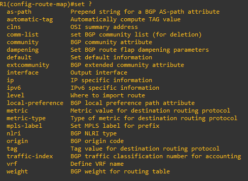
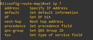
Step 3: Configure Route-map that will match the Access-list and set Action:
We created route-map on router R1 that will permit IP address matched in the ACL Match-UDP previously created.
Then we set up the next hop to 10.10.2.2 which is the router R3:
route-map GOTO-R3 permit 10
match ip address Match-UDP
set ip next-hop 10.10.2.2
Step 4: Apply the Route map on the incoming interface which is connected to PC1 :
interface Ethernet0/0
ip address 172.16.88.1 255.255.255.0
ip policy route-map GOTO-R3
Verifications:
- show ip policy
- show route-map
- traceroute
- debug ip policy
R1#show ip policy
Interface Route map
Ethernet0/0 GOTO-R3
Show route-map:

- before applying PBR:
we can see that the PBR applied on the incoming interface overridden the routing protocol (OSPF, even we applied cost to manipulate it).

- After Applying PBR:

This concludes our lab,

![Explore The BGP Path Selection Attributes [Explained with Labs]](https://learnduty.com/wp-content/uploads/2022/07/image-28-800x450.png)
