Cisco Nexus 9K Switches Architecture and Cloud Scale ASIC components Explained [Second Generation]
Reference note: This post consists of some notes from the actual Cisco white paper.
Contents
Introduction
This post present are the next generation of fixed Cisco Nexus 9000 Series Switches. The new platform, based on the Cisco Cloud Scale ASIC, supports cost-effective cloud-scale deployments, an increased number of endpoints, and cloud services with wire-rate security and telemetry.
We will start with the well known Cisco Nexus 93108-EX switch architecture.
A- Cisco Nexus 9300-EX Switches Architecture
The Cisco Nexus 9300-EX platform switches are built with Cisco’s Cloud Scale ASIC LSE. The Cloud Scale ASICs are manufactured using 16- nanometer (nm) technology, whereas merchant silicon ASICs are manufactured using 28-nm technology. The 16-nm fabrication can place more transistors in the same size of die as that used for merchant silicon.
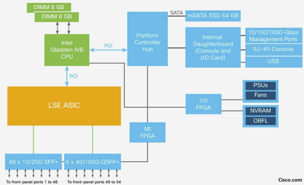
* Cisco Cloud Scale LSE ASIC Architecture
Cisco offers three types of its Cloud Scale ASICs: Cisco ACI Spine Engine 2 (ASE2), ASE3, and LSE. Their architecture is similar, but they differ in port density, buffering capability, forwarding scalability, and some features.
The LSE ASIC is a superset of ASE2 and ASE3 and supports Cisco ACI leaf switch and Fabric Extender (FEX) functions. Like the other Cloud Scale ASICs, the LSE uses a multiple-slice SOC design. The Cisco Nexus 9300-EX platform switches are built with the LSE ASIC.
Each ASIC has three main components:
- Slice components
- I/O components
- Global components
I- ASIC Slice components:
The slices make up the switching subsystems. They include multimode MAC addresses, packet parser, forwarding lookup controller, I/O packet buffering, buffer accounting, output queuing, scheduling, and output rewrite components.

The following Figures illustrate the ASIC components (from a Cisco Live presentation):
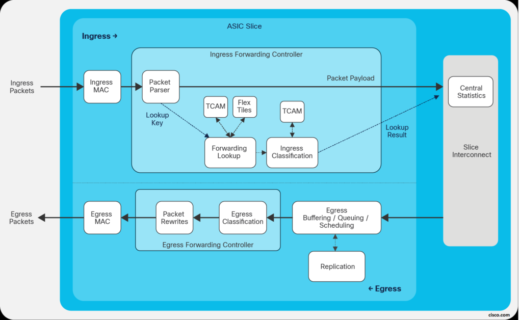
- Input Forwarding Controller:
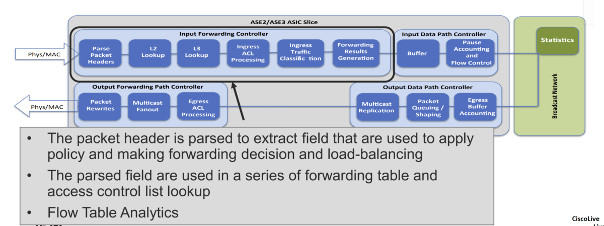
a- Packet parser:
When a packet enters through a front-panel port, it goes through the ingress pipeline, and the first step is packet-header parsing. The flexible packet parser parses the first 128 bytes of the packet to extract and save information such as the Layer 2 header, EtherType, Layer 3 header, and TCP IP protocol. This information is used for subsequent packet lookup and processing logic.
b- L2/L3 Lookup:
As the packet goes through the ingress pipeline, it is subject to Layer 2 switching and Layer 3 routing lookups. First, the forwarding process examines the Destination MAC address (DMAC) of the packet to determine whether the packet needs to be switched (Layer 2) or routed (Layer 3).
- If the DMAC matches the switch’s own router MAC address, the packet is passed to the Layer 3 routing lookup logic. If the DMAC doesn’t belong to the switch, a Layer 2 switching lookup based on the DMAC and VLAN ID is performed.
Inside the Layer 3 lookup logic, the Destination IP address (DIP) is used for searches in the Layer 3 host table. This table stores forwarding entries for directly attached hosts and learned /32 host routes. If the DIP matches an entry in the host table, the entry indicates the destination port, next-hop MAC address, and egress VLAN. If no match for the DIP is found in the host table, an LPM lookup is performed in
the LPM routing table.
c- Ingress ACL processing:
In addition to forwarding lookup processing, the packet undergoes ingress ACL processing. The ACL TCAM is checked for ingress ACL matches. Each ASIC has an ingress ACL TCAM table of 4000 entries per slice to support system internal ACLs and user-defined ingress ACLs.
d- Ingress traffic classification:
Cisco Nexus 9300-EX platform switches support ingress traffic classification. On an ingress interface, traffic can be classified based on the address field, IEEE 802.1q CoS, and IP precedence or Differentiated Services Code Point (DSCP) in the packet header.
The classified traffic can be assigned to one of the eight Quality-of-Service (QoS) groups. The QoS groups internally identify the traffic classes that are used for subsequent QoS processes as packets traverse the system.
e- Ingress forwarding result generation
The final step in the ingress forwarding pipeline is to collect all the forwarding metadata generated earlier in the pipeline and pass it to the downstream blocks through the data path. A 64-byte internal header is stored along with the incoming packet in the packet buffer.
This internal header includes 16 bytes of iETH (internal communication protocol) header information, which is added on top of the packet when the packet is transferred to the output data-path controller through the broadcast network. This 16-byte iETH header is stripped off when the packet exits the front-panel port. The other 48 bytes of internal header space are used only to pass metadata from the input forwarding queue to the output forwarding queue and are consumed by the output forwarding engine.
- Input Data Path Controller:
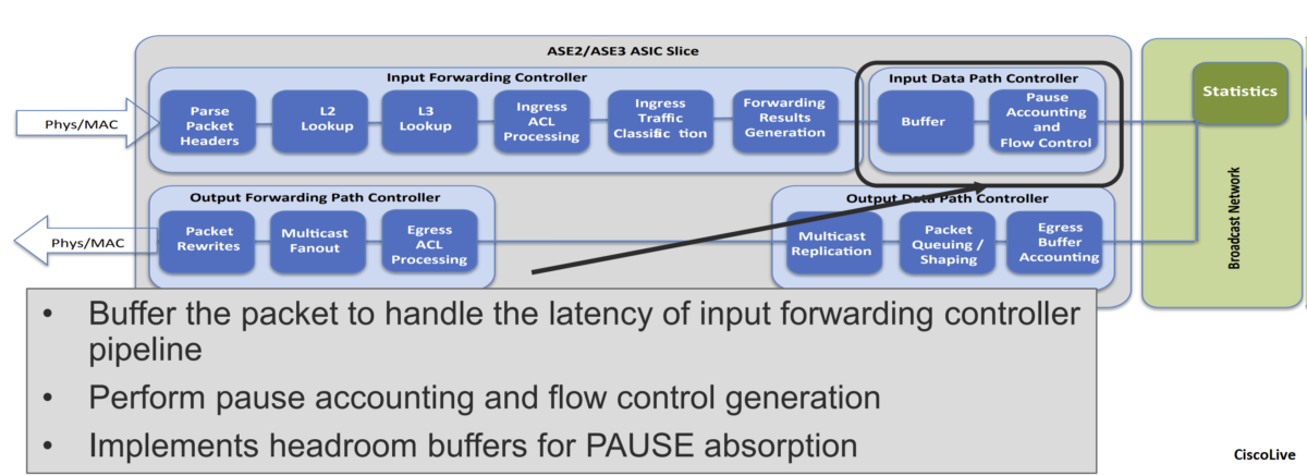
The input data-path controller performs ingress accounting functions, admission functions, and flow control for the no-drop CoS. The ingress admission-control mechanism determines whether a packet should be admitted into memory.
This decision is based on the amount of buffer memory available and the amount of buffer space already used by the ingress port and traffic class. The input data-path controller forwards the packet to the output data-path controller through the broadcast network.
- Broadcast Network (Inter-Slice):
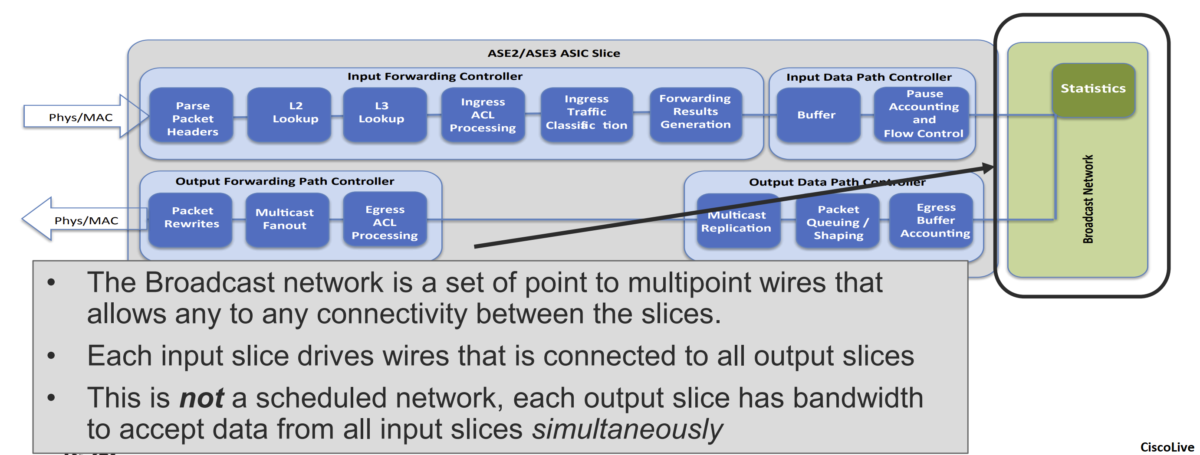
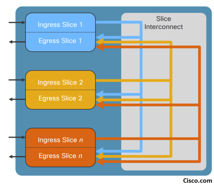
The broadcast network is a set of point-to-multipoint wires that allows connectivity between all slices on the ASIC. The input data-pathcontroller has a point-to-multipoint connection to the output data-path controllers on all slices, including its own slice.
The central statistics module is connected to the broadcast network. The central statistics module provides packet, byte, and atomic counter statistics.
- Output Forwarding Path Controller
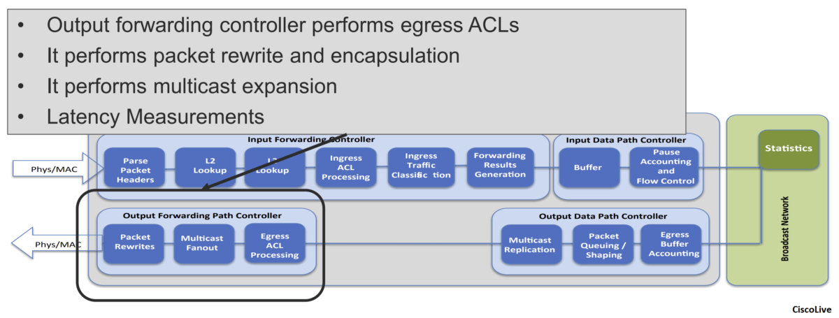
\The output forwarding controller receives the input packet and associated metadata from the buffer manager and is responsible for all packet rewrite operations and application of egress policy. It extracts internal header information and various packet-header fields from the packet, performs a series of lookups, and generates the rewrite instructions
II- I/O components:
The I/O components consist of high-speed Serializer/Deserializer (SerDes) blocks. These vary based on the total number of ports. They determine the total bandwidth capacity of the ASICs.
III- Global components:
The global components consist of the PCIe Generation 2 (Gen 2) controller for register and Enhanced Direct Memory Access (EDMA) access and a set of point-to-multipoint wires to connect all the slices together. Components also include the central statistics counter modules and modules to generate core and MAC address clocks.
LSE ASICs use a shared hash table known as the Unified Forwarding Table (UFT) to store Layer 2 and Layer 3 forwarding information. The UFT size is 544,000 entries on LSE ASICs. The UFT is partitioned into various regions to support MAC addresses, IP host addresses, IP address Longest-Prefix Match (LPM) entries, and multicast lookups. The UFT is also used for next-hop and adjacency information and Reverse-Path Forwarding (RPF) check entries for multicast traffic.
The UFT is composed internally of multiple tiles. Each tile can be independently programmed for a particular forwarding table function. This programmable memory sharing provides flexibility to address a variety of deployment scenarios and increases the efficiency of memory resource utilization.
In addition to the UFT, the ASICs have a 12,000-entry Ternary Content-Addressable Memory (TCAM) that can be used for forwarding lookup information.
The slices in the LSE ASICs function as switching subsystems. Each slice has its own buffer memory, which is shared among all the ports on this slice. Only ports within that slice can use the shared buffer space.
To efficiently use the buffer memory resources, the raw memory is organized into 208-byte cells, and multiple cells are linked together to store the entire packet. Each cell can contain either an entire packet or part of a packet
B- Cisco Nexus 9300-EX Switches Architecture
The Cisco Nexus 9500 Series switches have a modular design, it include mainly the following components:
- Supervisor engine
- System controllers
- Fabric modules
- Line cards

System Controller Module
• Redundant half-width system controller
• Offloads supervisor from device management tasks
Increased system resiliency
Increased scale
• Performance- and scale-focused
Dual core ARM processor, 1.3 GHz
• Central point-of-chassis control
• Ethernet Out of Band Channel (EOBC) switch:
1 Gbps switch for intra-node control plane communication
(device management)
• Ethernet Protocol Channel (EPC) switch:
1 Gbps switch for intra-node data plane communication
(protocol packets)
• Power supplies through system management bus (SMB)
The System Controllers are the intra-system communication central switches. It hosts two main control and management communication paths, Ethernet Out-of-Band Channel (EOBC) and Ethernet Protocol Channel (EPC), between supervisor engines, line cards and fabric modules.
All intra-system management communication across modules takes place through the EOBC channel. The EOBC channel is provided via a switch chipset on the System Controllers that inter-connects all modules together, including supervisor engines, fabric modules and line cards.
The EPC channel handles intra-system data plane protocol communication. This communication pathway is provided by another redundant Ethernet switch chipset on the System Controllers. Unlike the EOBC channel, the EPC switch only connects fabric modules to supervisor engines. If protocol packets need to be sent to the supervisors, line cards utilize the internal data path to transfer packets to fabric modules. The fabric modules then redirect the packet via the EPC channel to the supervisor engines.
The System Controller also communicates with and manages power supply units and fan controllers via the redundant system management bus (SMB).
The Cloud Scale fabric modules in the Cisco Nexus 9500 platform switches provide high-speed data-forwarding connectivity between the line cards. In some cases, the fabric modules also perform unicast or multicast lookups, and provide a distributed packet replication function to send copies of multicast packets to egress ASICs on the line cards.
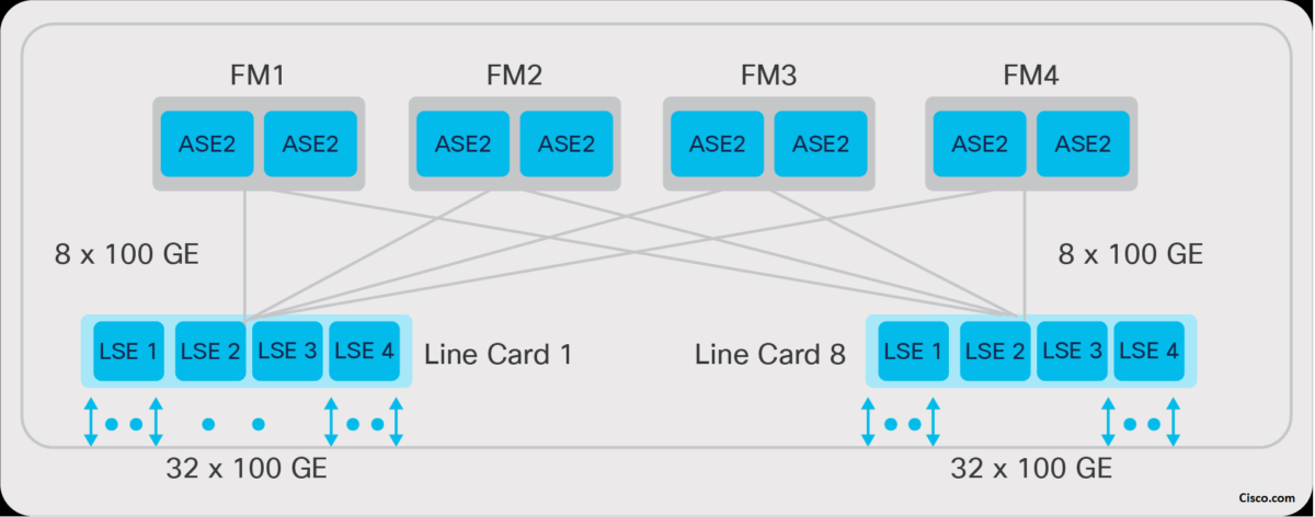
The Cisco Nexus 9500 Cloud Scale line cards provide the front-panel interface connections for the network and connect to the other line cards in the system through the Cloud Scale fabric modules. Cloud Scale line cards consist of multiple ASICs, depending on the required port types and density – for example, 10/25-Gbps line cards use two ASICs, while 100-Gbps line cards use four. The line card ASICs perform the majority of forwarding lookups and other operations for packets ingressing or egressing the system, but the fabric modules may perform certain functions as well in a distributed and scalable fashion.
In addition to the ASIC resources used for high-performance data-plane packet forwarding, Cisco Nexus 9500 Cloud Scale line cards have an on-board dual-core x86 CPU as well. This CPU is used to offload or speed up some control-plane tasks, such as programming the hardware tables, collecting line-card counters and statistics, and offloading Bidirectional Forwarding Detection (BFD) protocol handling from the supervisor.

![Explore The BGP Path Selection Attributes [Explained with Labs]](https://learnduty.com/wp-content/uploads/2022/07/image-28-800x450.png)
