Cisco ACI Service Graph PBR Configuration [Step by Step]
Contents
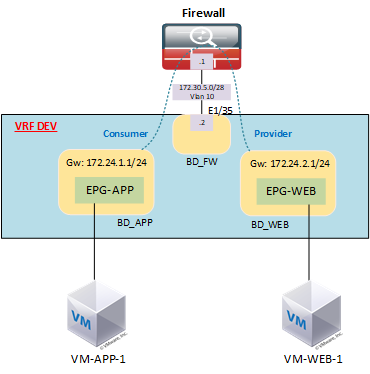
Topology
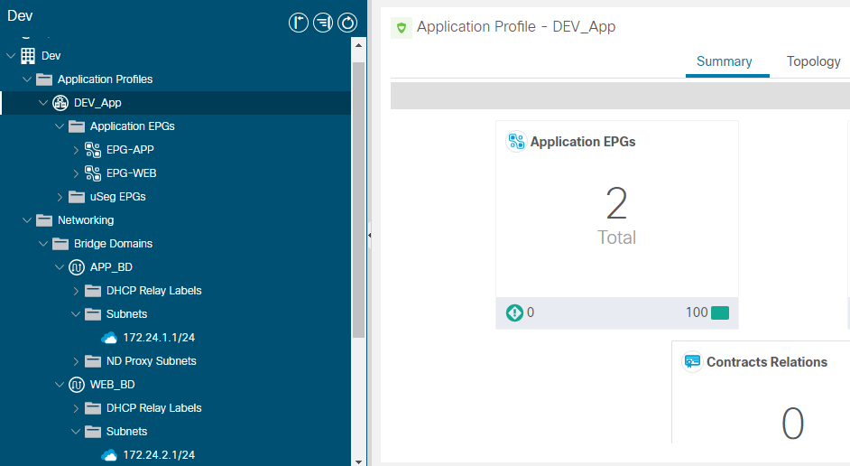
Step-1: Configure The APP and WEB EPGs, BD (pre-config):
We have the APP and WEB EPGs and Bridge domains already configured, please refer to this post for EPG basic configuration.
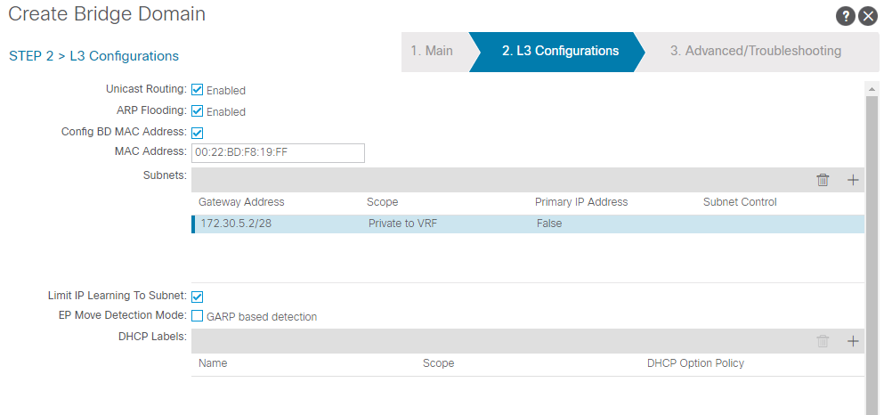
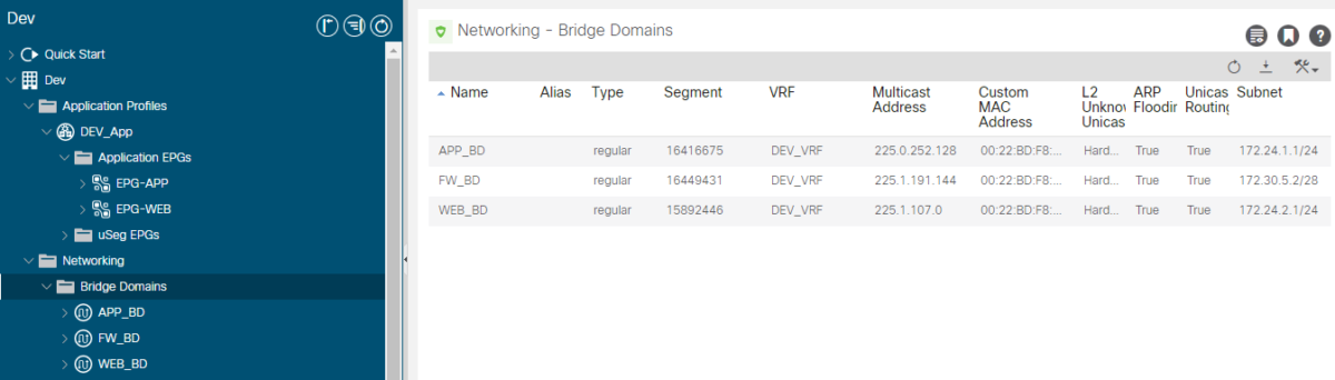
Step-2: Configure the Firewall Bridge Domain:

We configure the subnet under the bridge Domain as it will serve as the next hop for the firewall, since, we are willing to configure service graph Go-to mode:
Let’s dive into Service graph PBR configuration:
- Create L4-L7 Device
- Create Service graph template
- Apply L4-L7 Service graph template
Step-3: Create L4-L7 Device
Navigate to Tenant > Services > L4-L7 > Devices > right click “Create L4-L7 Devices”
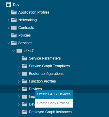
Fill the Device parameters, and chose the interface connected to the FW:
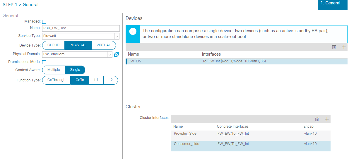
One Arm cluster Interfaces
Although PBR node has one interface, the device selection policy has both consumer and provider connector configuration settings.
For a one-arm mode service graph, you just select the same options for both the consumer and provider connectors in the device selection policy, so that only one segment is deployed for the one interface during service graph instantiation.
Step-4: Create Service graph Template
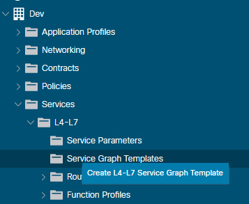
Navigate to Tenant > Services > L4-L7 > Service graph Templates (right click Create L4-L7 Service Graph Template):
- Enter the Service Graph name, then Drag and Drop the Device previously created, Also select Firewall type routed with route redirect checked and submit:
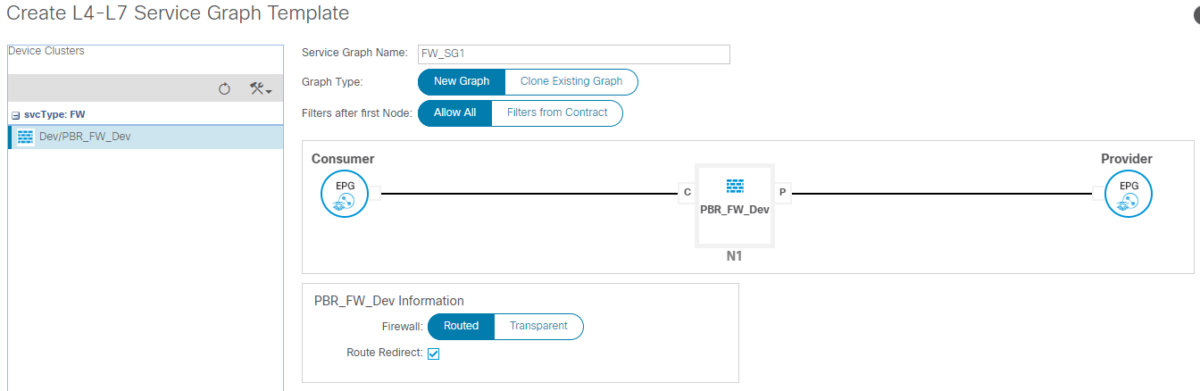
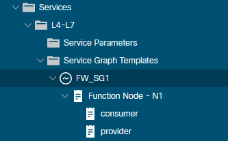
Now, you will see a Service graph template added and the Device have 2 connectors (consumer and provider) which represent the shadow EPG contracts.
The consumer connector is linked to the consumer EPG and the provider connector:
Step-5: Apply L4-L7 service graph Template
Expand the service graph Templates menu, right click on the created template and select “Apply L4-L7 service graph Template”:
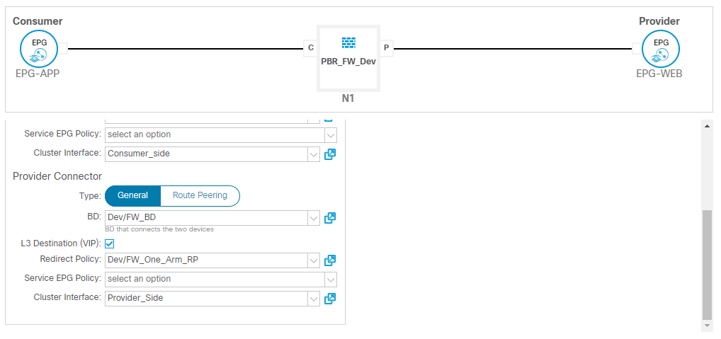
Select the consumer and the provider EPGs and enter the contract name:
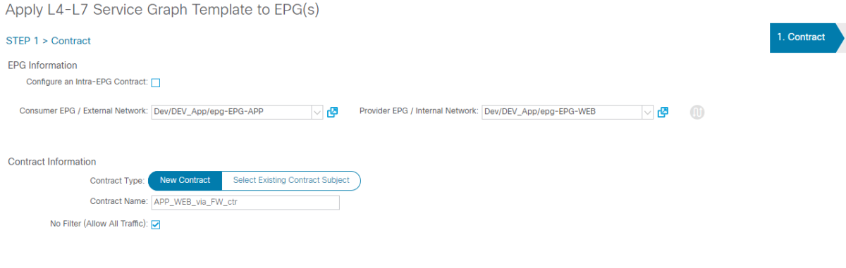
Select the consumer and the provider connectors which include:
- Bridge domain (in one arm scenario, we use the same BD: FW_BD)
- chose the cluster Interface (refer to the Interface cluster created when configuring L4-L7 device, we have created two interface clusters (consumer_side and provider_side), even if they contain the same concrete interfaces (access, PC or vPC).
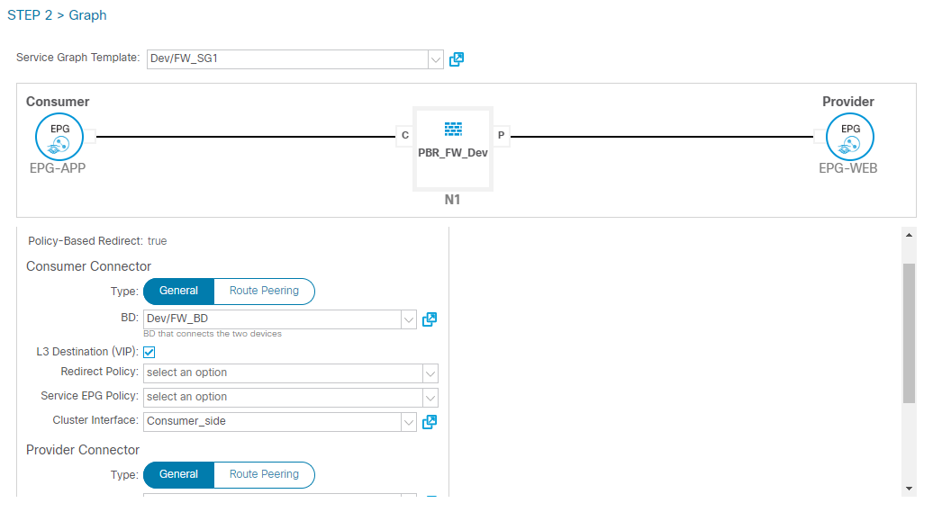
At this stage, we also need to create a “Redirect Policy” in which we will define the next hop for the PBR policy (FW interface IP and MAC):
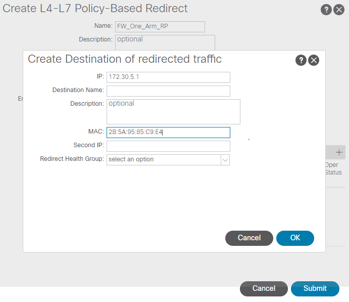
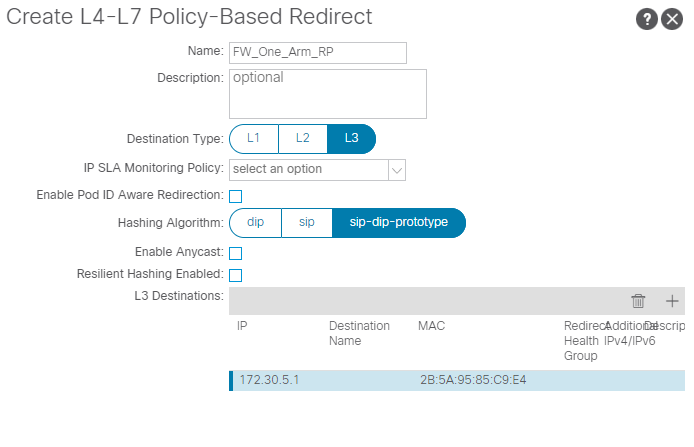
Provider side:
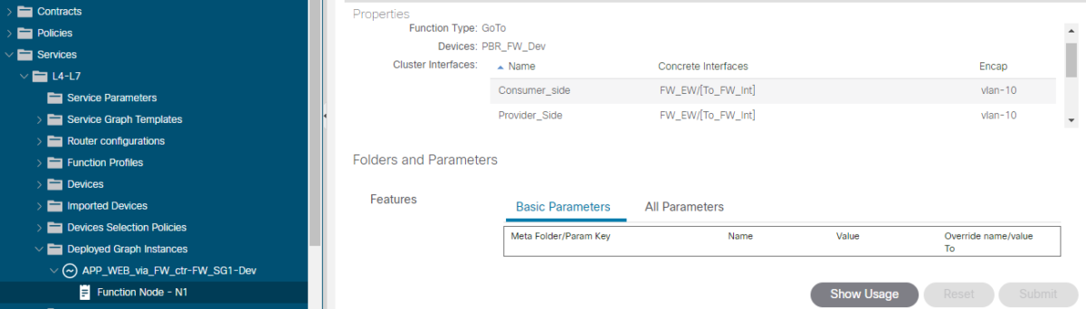
We can verify the configuration, under “Deployed Graph Instances”: