Cisco ACI SAN FC (Fiber Channel) and FCoE Configuration
Contents
- Fibre Channel N-Port Virtualization Supported Hardware
- Convert Ethernet port to FC port on ACI
- I- Fibre Channel (FC) Access Policies Configuration on ACI
- II- Fibre Channel over Ethernet (FCoE) Access Policies Configuration
- Step-1: Create VLAN Pool for FCoE:
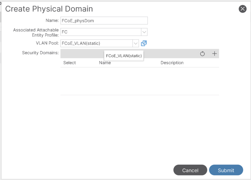
- Step-2: Create Physical Domain for FCoE:
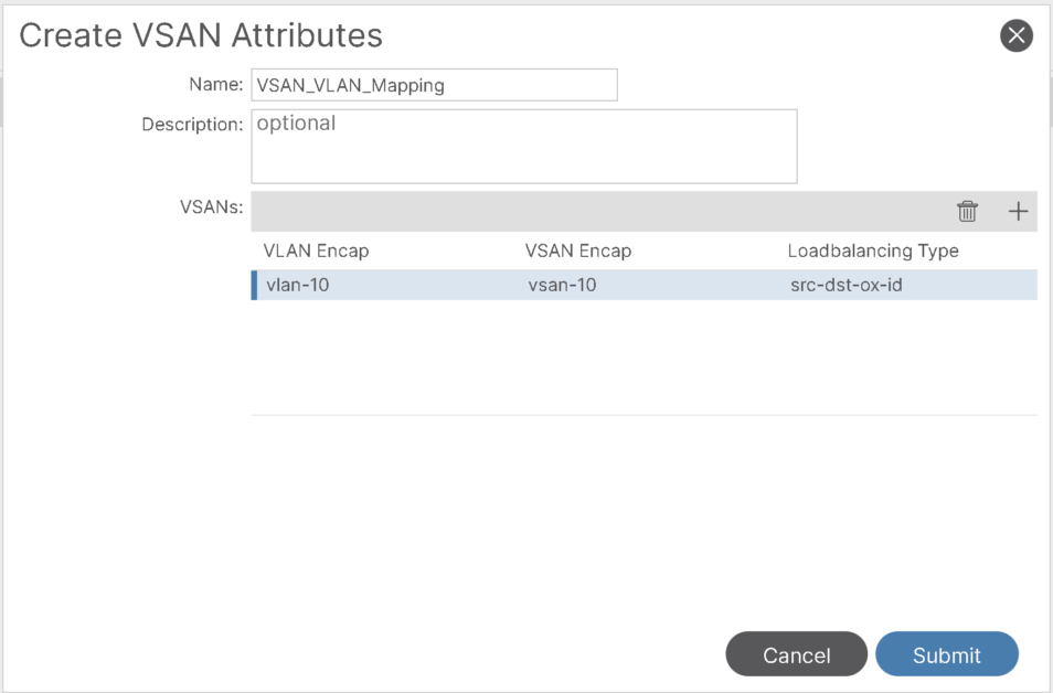
- Step-3: Modify the FC Domain and map VSAN to corresponding VLAN:
- Step-4: Add FC Domain and FCoE physical Domain to the AAEP used for Server:
- Step-5: Enable Priority Flow Control for FCoE:
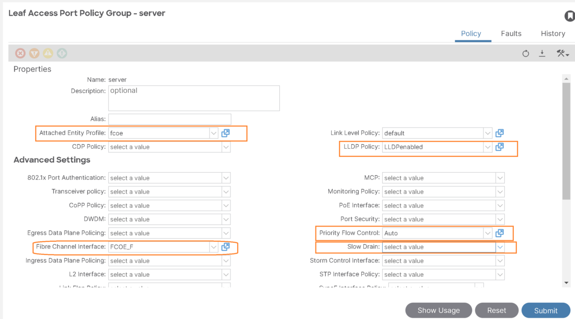
- Step-6: Configure/tune Interface policy group used for the server:
- III- FC and FCoE Tenant configuration
Fibre Channel N-Port Virtualization Supported Hardware
Fibre Channel N-Port Virtualization (FC NPV) is supported on the N9K-C93180YC-FX switch and only the following FC SFPs are supported:
- DS-SFP-FC8G-SW: 2/4/8G (2G is not a supported FC NPV port speed)
- DS-SFP-FC16G-SW: 4/8/16G (not compatible when FC NPV port speed is 32G)
- DS-SFP-FC32G-SW: 8/16/32G (not compatible when FC NPV port speed is 4G)
Supported NPIV core switches are Cisco Nexus 5000 Series, Nexus 6000 Series, Nexus 7000 Series (FCoE), and Cisco MDS 9000 Series Multilayer Switches.
Convert Ethernet port to FC port on ACI
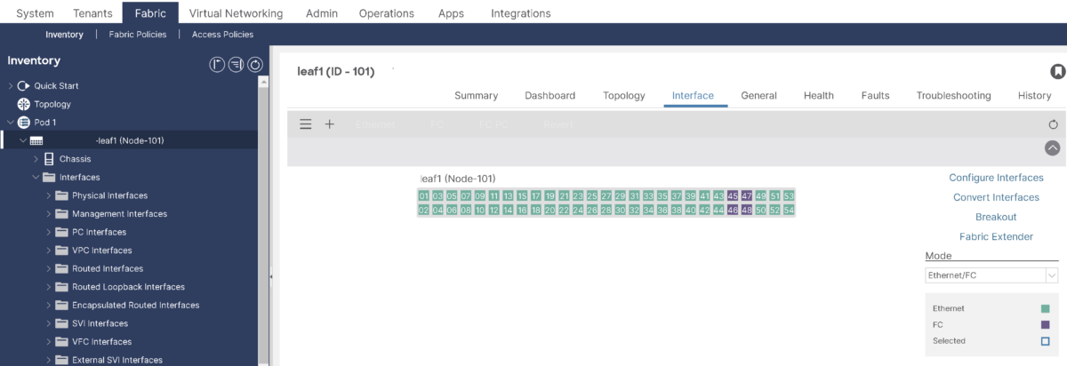
To convert Ethernet to FC port, you need to perform in a group of 4:
apic1(config)# leaf 101
apic1(config-leaf)# slot 1
apic1(config-leaf-slot)# port 45 48 type fcCode language: PHP (php)
This example converts ports 1/45-48 on leaf 101 to Fibre Channel ports. The [no] form of the port type fc command converts the ports from Fibre Channel back to Ethernet.
Note:
- If you convert a port from Ethernet to Fibre Channel or the other way around, you must reload the switch. Currently, you can convert only one contiguous range of ports to Fibre Channel ports, and this range must be a multiple of 4, ending with a port number that is a multiple of 4. For example, 1-4, 1-8, or 21-24.
Target Topology:
I- Fibre Channel (FC) Access Policies Configuration on ACI
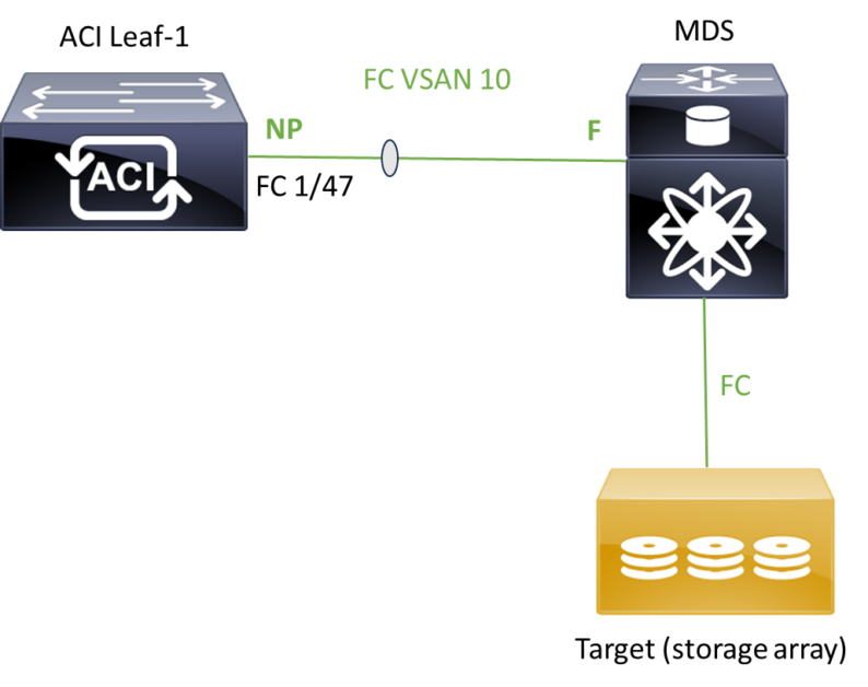
Topology:
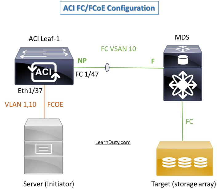
The first part of our topology for fiber channel looks like, ACI is NPV and MDS is core:
FC Access object models:
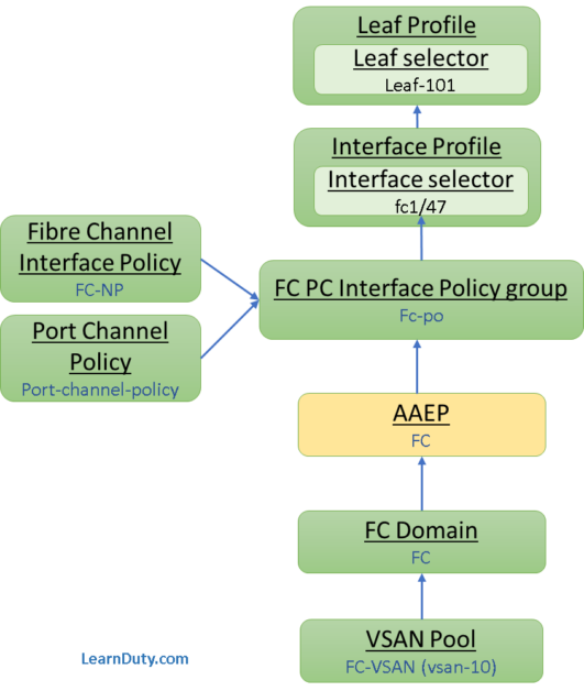
Below is the objects that we will create for the FC access policies configuration:
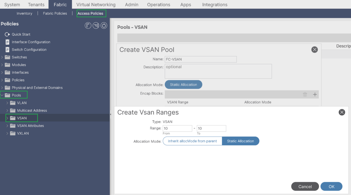
Step-1:Create VSAN Pool:
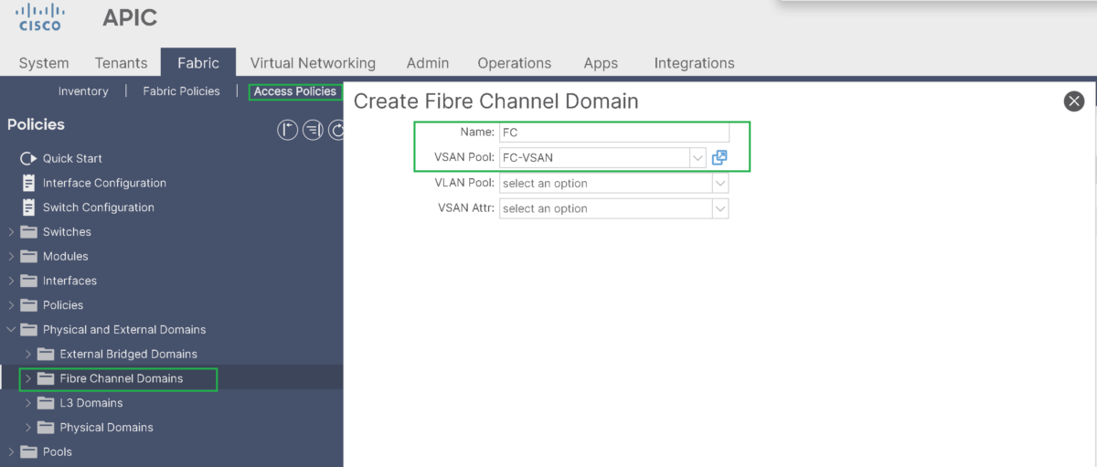
Step-2: Create Fiber Channel Domain:
Create Fibre Channel Domain and associate the previously created VSAN Pool to it:
Step-3: Create AAEP:
Create an AAEP and associate the Fibre Channel Domain to it:
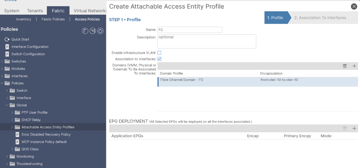
Step-4: Create FC PC Interface Policy Group:
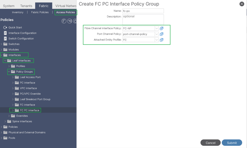
Under the FC PC Interface policy group:
– Specify the Port-channel policy (using LACP active)
– Select the created AAEP
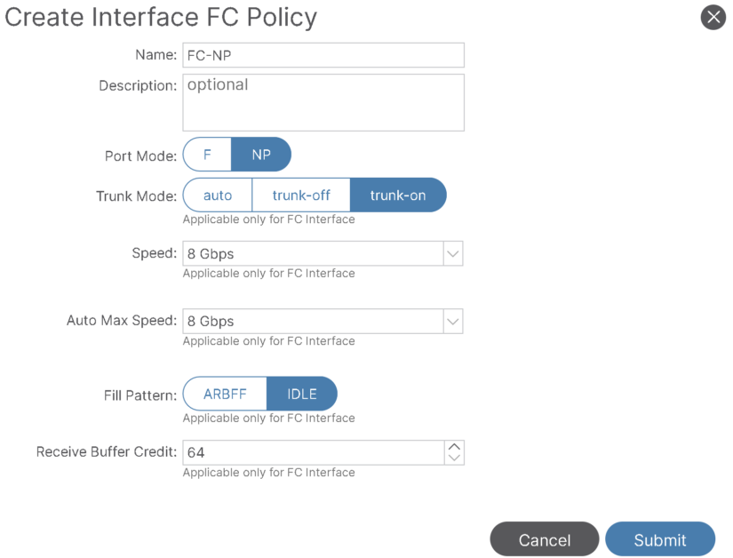
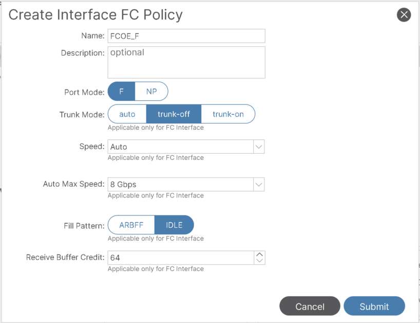
– Specify the Fibre channel Interface policy where we define:
- The Port Mode (NP port because fc1/47 is connected to core device), or F port in case it’s connected to host.
- Trunking: On, because we plan to use multiple VSAN on this FC PC.
- The link speed (8 Gbps)
- Fill Pattern: Nexus 9000 only supports the IDLE fill pattern on 8 Gbps Fibre Channel interfaces
For Nexus 9000 FC interface to operate at 8 Gbps, peer device must be configured to use a matching IDLE fill pattern.
(Note: when switch not sending/receiving on FC interface, it will send IDLEs to fill this quit periods)
Step-5: Create SAN Interface Profile and Interface selector:
Interface Profile:
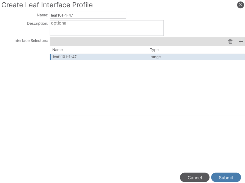
Interface selector:
Map it to the previously create FC PC Interface policy group:
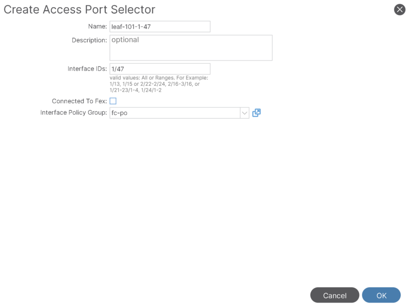
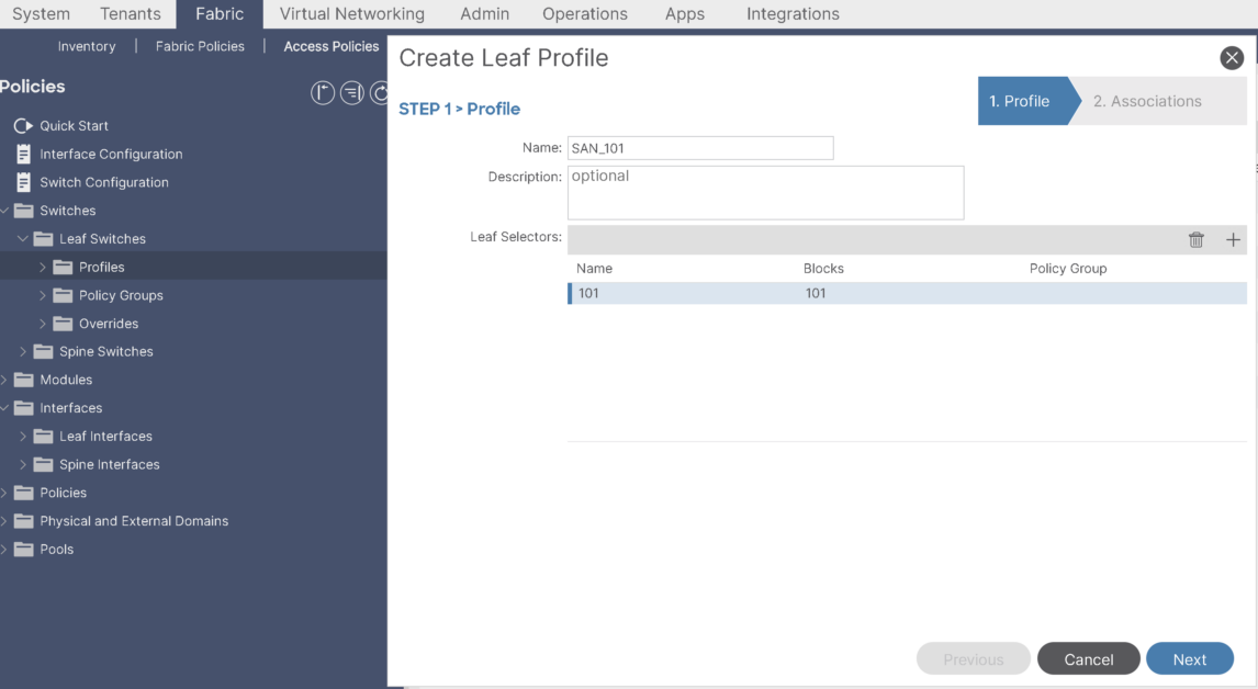
Step-6: Create SAN leaf Profile and Leaf selector:
Leaf-Profile and Leaf selector:
Associate the Leaf Profile to the Interface profile:
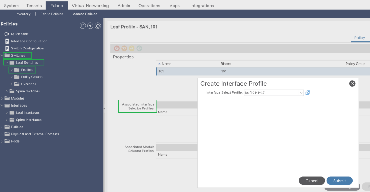
That would conclude the Access policies configuration for FC PC port connected to the MDS switch.
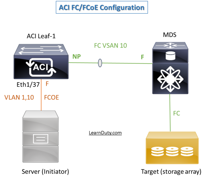
II- Fibre Channel over Ethernet (FCoE) Access Policies Configuration
Topology:
Access Policies:

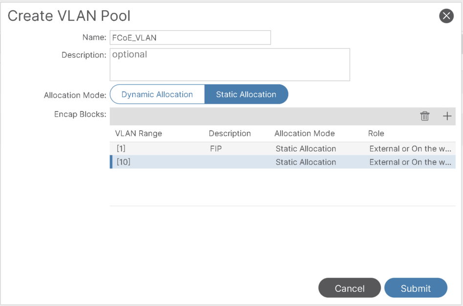
Step-1: Create VLAN Pool for FCoE:
This will include VLAN 10 that will mapped to vsan 10 and vlan-1 to be used as native VLAN for FIP:
Step-2: Create Physical Domain for FCoE:
Step-3: Modify the FC Domain and map VSAN to corresponding VLAN:
1- Under the already created FC Domain, select the VLAN Pool including the VLAN 10 used for FCoE:

2- For VSAN Attr, create a mapping for VLAN to VSAN:
Step-4: Add FC Domain and FCoE physical Domain to the AAEP used for Server:
We will use the same AAEP, but, you can create a new AAEP for FCoE interface if needed:
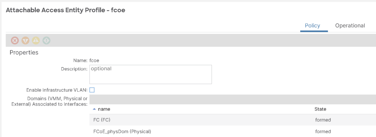
Assuming we already have Eth1/37 has remaining access policies already configured (including interface policy group, interface profile etc).
Step-5: Enable Priority Flow Control for FCoE:
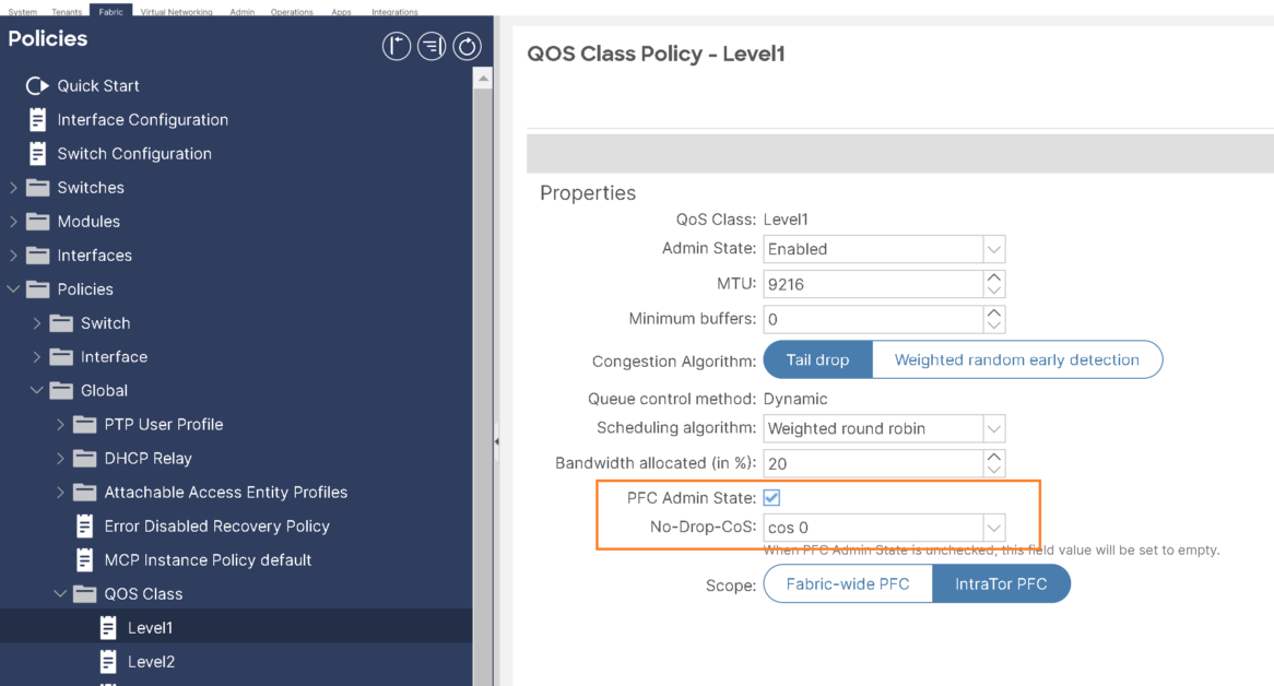
To ensure we have lossless ethernet, Enable a no-drop policy for this level of FCoE traffic designated with a certain Class of Service (CoS) level.
Note:
- QoS level enabled for PFC and FCoE no-drop must match with the Priority Group ID enabled for PFC on CNA.
- Only one QoS level can be enabled for no-drop and PFC, and the same QoS level must be associated with FCoE EPGs.
we will use cos0 as no drop CoS:
Step-6: Configure/tune Interface policy group used for the server:
- Priority Flow Control Policy: Specifies the state of priority flow control (PFC) on the interfaces to which this policy group is applied. This policy specifies under what circumstances QoS-level priority flow control will be applied to FCoE traffic.
- Fibre Channel Interface Policy: specify F port.
- Slow Drain Policy: Specifies the policy for handling FCoE packets that are causing traffic congestion on the ACI Fabric.
- Make sure LLDP enabled for DCBX and FIP to work properly.
III- FC and FCoE Tenant configuration
Assuming tenant and VRF already configured, create a new EPG and BD to be used for VSAN-10:
Tenant Configuration for FC Uplinks:
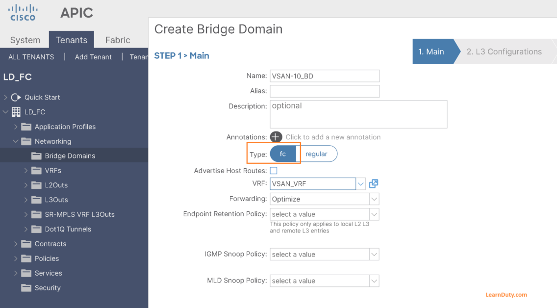
1- Create BD For VSAN-10:
- Select BD type as fc and select VRF:
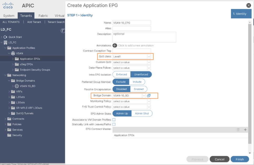
2- Create EPG for VSAN-10
- Select created BD and select Qos class with PFC enabled:
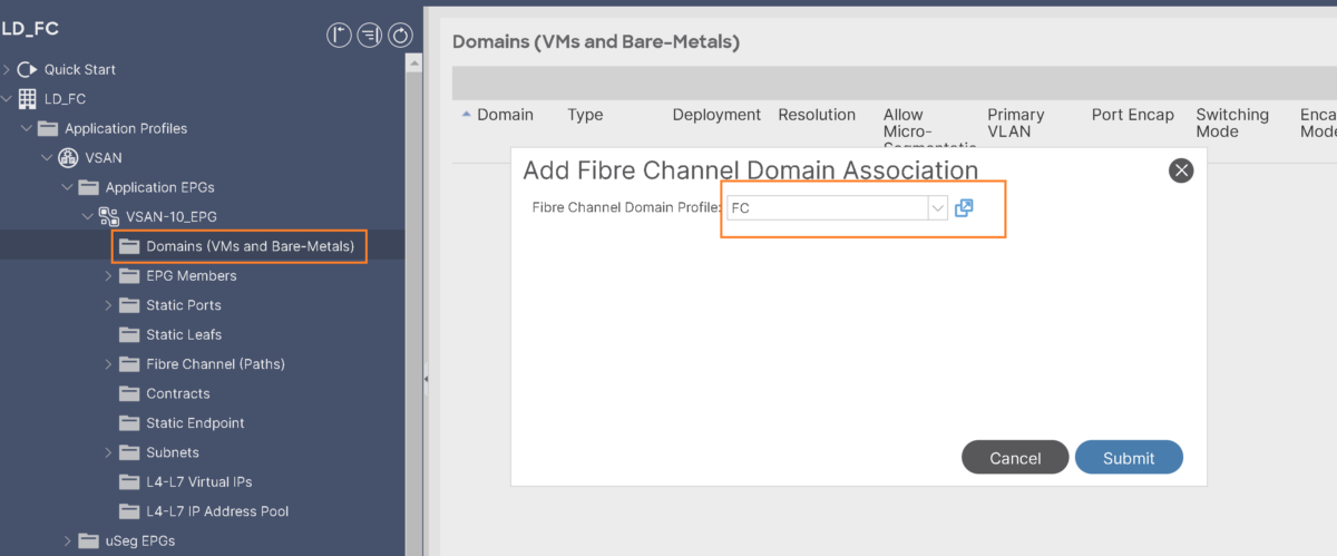
- Associate FC domain to the EPG:
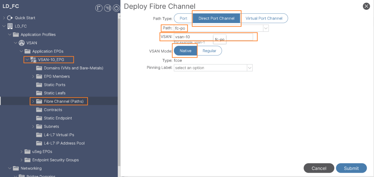
- Add FC path under the EPG:
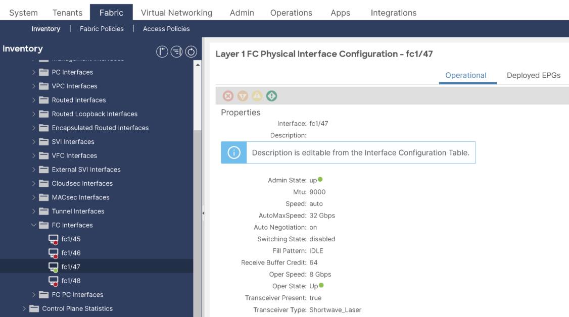
At this point, we can see the fc1/47 operational state is UP:
Tenant Configuration for FCoE to the server:
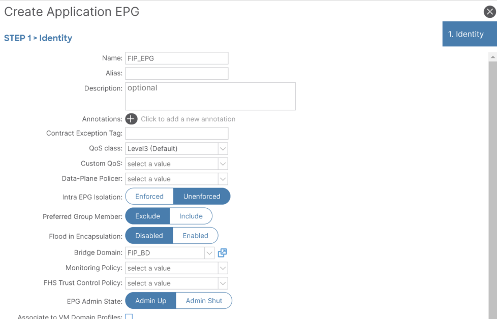
1- FIP EPG:
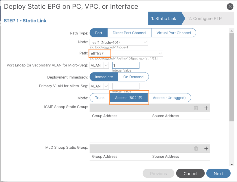
Create an EPG to be used for FIP which will have path with native (802.1P) VLAN and FCoE physical domain associated.
It’s regular EPG and regular VLAN to allow native VLAN to flow:
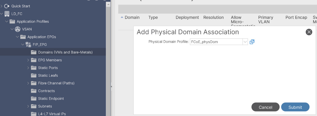
Allow VLAN as untagged with 802.1P:
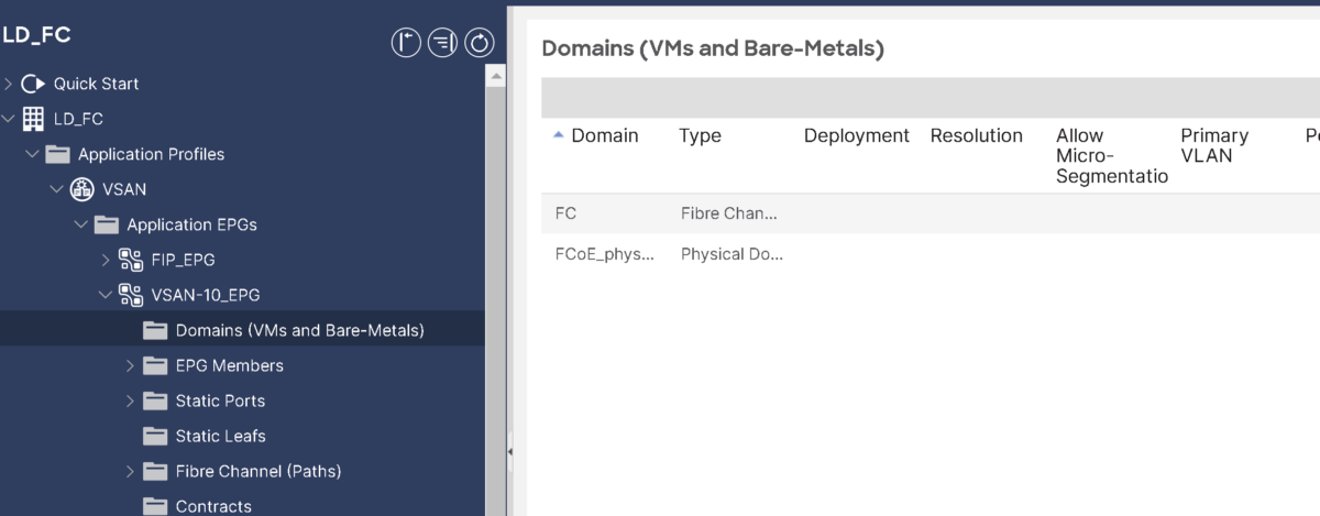
2- Add FCoE Physical domain association to VSAN-10 EPG:
because we need to add Interface to the server under the VSAN-10 EPG to have the vsan flowing through it:
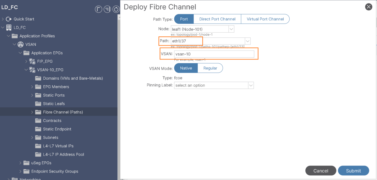
Add Eth1/37 (interface toward the server) as fibre channel path under VSAN-10 EPG:
- Specify vsan-10 for this path:
Then FIP is working properly, it should be able to instantiate a vFC interface vfc1/37 corresponding to eth1/37.
That’s basically it.
Please refer to following official guidelines for more details.

