Cisco ACI L2OUT Configuration Example [Explained]
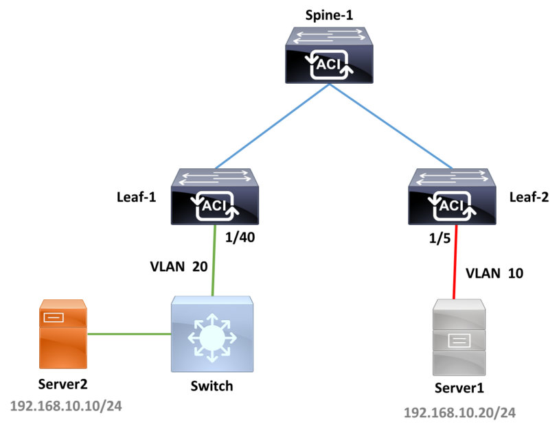
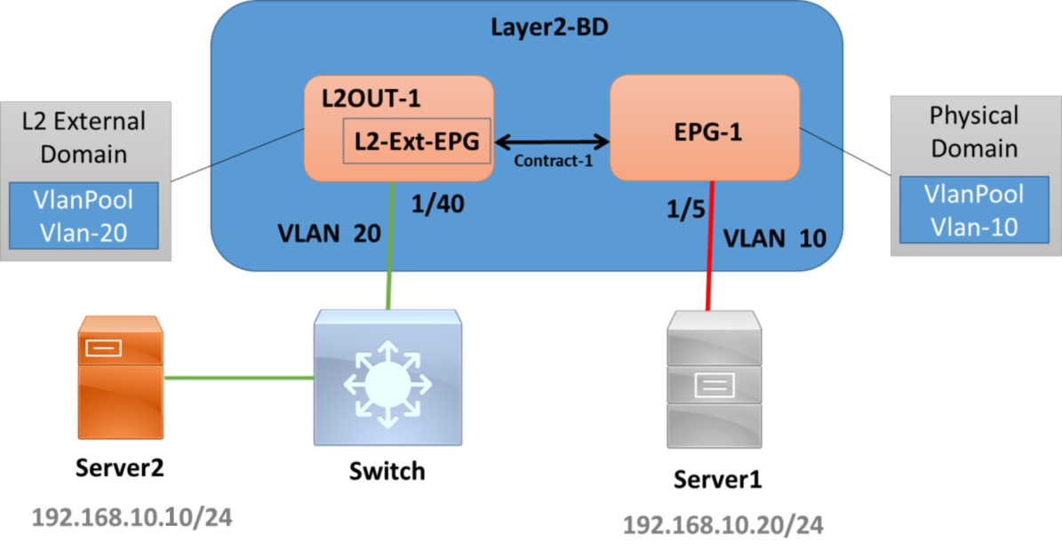
- Physical Topology:
In our topology, we are going to enable L2 connectivity between server-1 and server-2:
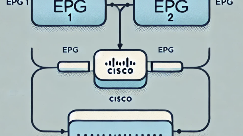
- Logical Topology:
- Configuration Steps:
We are assuming that the access policies is configured and we will only mention Tenant policies for L2OUT configuration
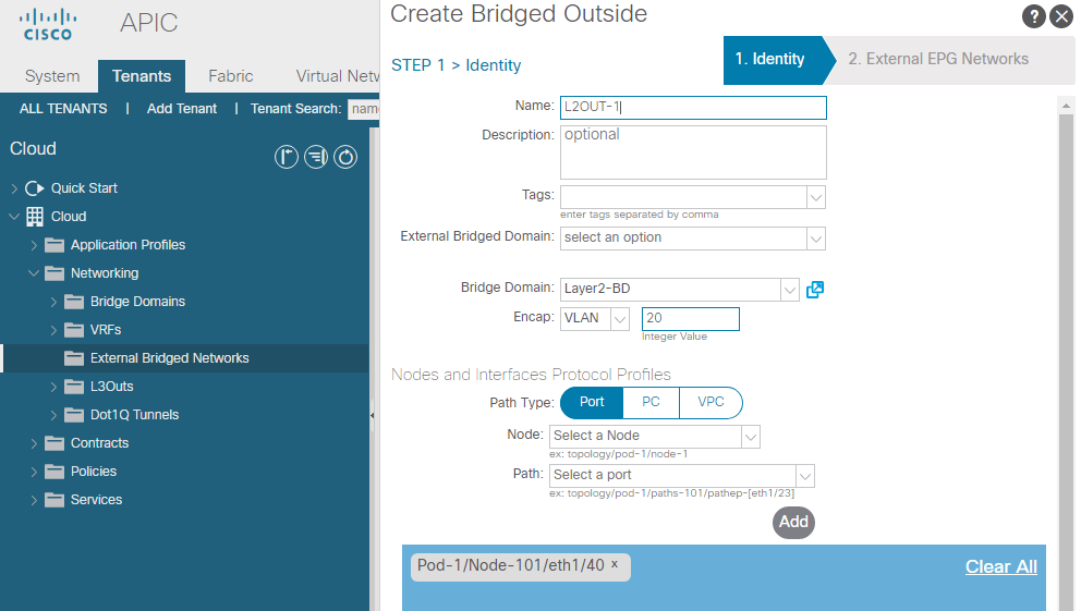
1- Create an External Bridged Network (L2OUT)
- Enter the name: L2OUT-1
- Select the External L2 Domain (not mentioned in screenshot, It should be selected, equivalent to EPG domain association)
- Select the Bridge domain to Extend: Layer2-BD
- VLAN: 20 (this Encap must match the external device encapsulation)
- select the path to the external device: 1/40 on leaf-1.
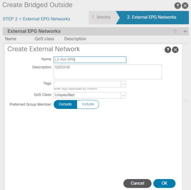
2- Create an External L2OUT EPG:
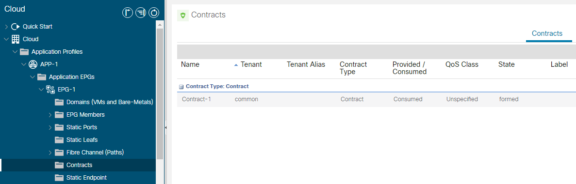
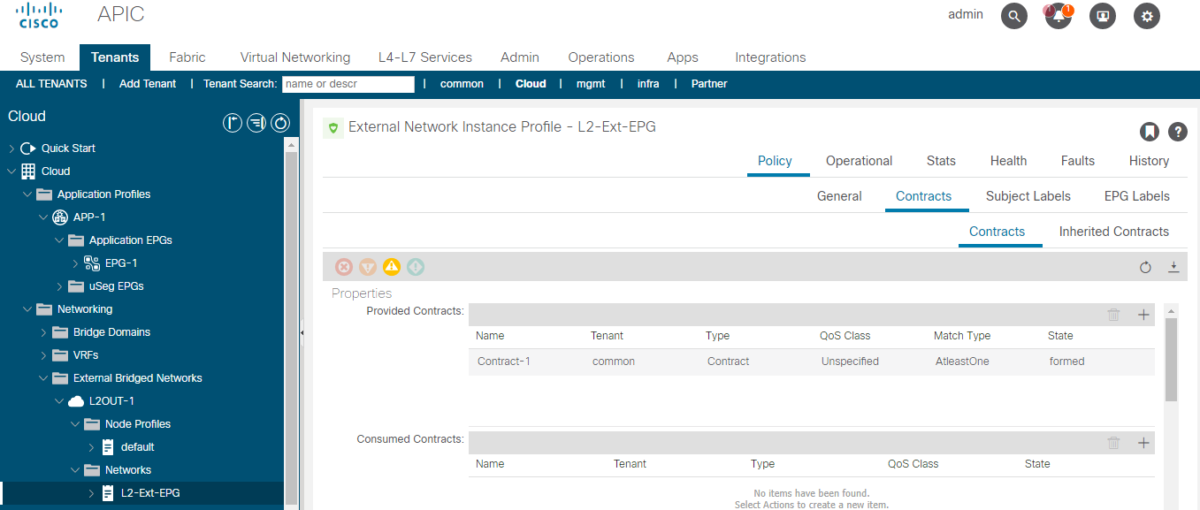
3- Provide the contract at The L2OUT External EPG:
This can be consumed or provided depending on the Endpoint communication policies:
4- Consume the contract at the internal EPG side: