How to Setup ELAM Capture in ACI
Contents
What is Cisco ACI ELAM tool
Embedded Logic Analyzer Module (ELAM) is a tool that allows a user to set conditions in hardware and capture the first packet or frame that matches the set conditions. A successful capture will cause the ELAM status to show as ‘triggered’. Once triggered, the ELAM is disabled and a dump can be collected to analyze the vast number of forwarding decisions that the switch ASIC is making with that packet/frame.
ELAM is a tool that gives you the ability to look inside Cisco ASICs and understand how a packet is forwarded. It is embedded within the forwarding pipeline, and it can capture a packet in real-time without disruptions to performance of CPU or the control-plane resources. It helps to answer questions such as:
- Did the packet reach the Forwarding Engine (FE)?
- On what port and VLAN is the packet received?
- How does the packet appear (Layer 2 (L2) – Layer 4 (L4) data)?
- How is the packet altered, and where is it sent?
ELAM is extremely powerful, granular, and non-intrusive. It is a valuable troubleshooting tool for Cisco Technical Assistance Center (TAC) engineers who work on hardware-switching platforms.
Each platform follows a similar workflow, as shown in this diagram:

- Identify the expected ingress FE. When platforms have more than one FE, it is critical to identify the FE that makes the forwarding decision for the packet you want to capture. Configure the ELAM on the correct FE.
- Configure the ELAM trigger. You must configure a trigger with details specific to the packet that you want to capture. Common triggers include a source and destination IP address or L4 port numbers. ELAM allows multiple fields to be specified and performs a logical AND on all fields configured.
- Start the ELAM.
- Wait for the ELAM to trigger and display the result.
I- ELAM on the First Generation Switches:
There are two ASIC types on Nexus 9300: Broadcom Trident T2 and the Cisco Northstar ASIC
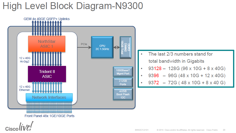
- Northstar: ns: – Gen1
- Alpine: alp – Spines
- Rocky: roc – F/FX/FXP
- Tahoe: tah – GC/E/EX
Some considerations before using ELAM (@arielik):
- ELAM operates only in the Northstar ASIC for leafs (Gen1).
- ELAM operates only in the Alpine ASIC for Spines.
- Any packets that are locally switched in the BCM ASIC will not trigger the ELAM, since in this scenario the packet will not reach Northstar, and will not trigger an ELAM event.
- We must be sure that the packet is sent from the BCM ASIC to the Northstar ASIC.

II- ELAM on the Second Generation Switches:
The second generation switches leverages the Cisco Cloud Scale ASICs:

ACI ELAM Basic Syntax:
- We will first look at the syntax of the ELAM on ACI switches and what’s the purpose of each command:
vsh_lc                                       [This command enters the line card shell where ELAMs are run]
debug platform internal <asic> elam asic 0   [refer to the ASICs table]

trigger reset                                           [ensures no existing triggers are running]
trigger init in-select <number> out-select <number>     [determines what information about a packet is displayed and which conditions can be set]
set outer/inner                                         [sets conditions]
start                                                   [starts the trigger]
status                                                  [checks if a packet is captured]

ereport             [display detailed forwarding decision for the packet]
ELAM Configuration Example Configuration:
- Let’s take an example of ELAM configuration and then go through the configuration step by step:
module-1# debug platform internal tah elam asic 0
module-1(DBG-elam)# trigger reset
module-1(DBG-elam)# trigger init in-select 6 out-select 0
module-1(DBG-elam-insel6)# set outer ipv4 src_ip 10.0.0.1 dst_ip 10.0.0.2
module-1(DBG-elam-insel6)# start
module-1(DBG-elam-insel6)# status

module-1(DBG-elam-insel6)# ereport
trigger reset
- Input Select command: “in-select”:
The ‘in-select’ defines which headers the packet/frame is expected to have, and which to match on.
☑Examples:
A packet coming from a downlink port that is not VXLAN encapsulated would only have outer Layer 2, Layer 3, and Layer 4 headers.
A packet coming from a front-panel (downlink) port that is VXLAN encapsulated (such as Cisco ACI Virtual Edge in VXLAN mode) or coming from an upstream spine would have VXLAN encapsulation. This means it would have potentially both outer and inner Layer 2, Layer 3, and Layer 4 headers.
☑ Input Select Lines:
module-1(DBG-elam)# trigger init in-select ?
 10  Outerl4-innerl4-ieth
 13  Outer(l2|l3|l4)-inner(l2|l3|l4)-noieth
 14  Outer(l2(vntag)|l3|l4)-inner(l2|l3|l4)-ieth
 15  Outer(l2|l3|l4)-inner(l2|l3|l4)-ieth
 6   Outerl2-outerl3-outerl4
 7   Innerl2-innerl3-innerl4
 8   Outerl2-innerl2-ieth
 9   Outerl3-innerl3
☑ Coomon Usages and Best Practices:
- If ‘in-select 6’ is selected the only option is to set conditions and display headers from the outer Layer 2, 3, or 4 headers.
–> To capture a packet coming with VLAN encapsulation on a downlink port, use ‘in-select 6’
- If ‘in-select 14’ is selected the only option is to set conditions for and see the details of the outer and inner Layer 2, 3, and 4 headers.
–> To capture a packet with VXLAN encapsulation (either from a spine or from a vleaf with VXLAN encapsulation) use ‘in-select 14’
- Output Select command: “out-select”:
The ‘out-select’ allows some ability to control which lookup results are displayed in the ELAM report.
For most practical purposes ‘out-select 0′ can be used as it contains most information including the ‘drop vector‘ which will tell if the result of the lookup is to drop the packet/frame.
☑ Output Select Lines
0 – Pktrw
1 – Sideband
- ELAM Set conditions:
ELAM supports a large amount of Layer 2, 3, and 4 conditions to look for in a packet:
module-1(DBG-elam-insel6)# set outer ?
  arp   ARP Fields
  fc    FC Fields
  ipv4  IPv4 Fields
  ipv6  IPv6 Fields
  l2    All Layer 2 Fields
  l3    Layer 3 Fields
  l4    L4 Fields
  mpls  MPLS Fields

module-1(DBG-elam-insel6)# set outer l3 ?
  ether-type  ARP Ether Type - 0x0806 -> ARP 0x8035 -> RARP
  packet-len  Packet Total Length
Specifying ‘inner’ vs. ‘outer’ determines if the condition should be checked in the inner
header (VXLAN encapsulated packet) or outer header.
☑ Examples:
1- Source and destination outer MAC address, to capture packet from front ports (Not encapsulated packets) based on MAC addresses fields:
set [outer|inner] l2 [src_mac|dst_mac|...|]
2- Source and destination Outer IPv4 addresses, to capture packet from front ports (Not encapsulated packets):
set outer ipv4 src_ip 10.0.0.1 dst_ip 10.0.0.2
3- Source and destination Inner IP addresses, to capture packet VXLAN packets (mostly coming from spine, or could that EP sending VXLAN encapsulated traffic to the leaf):
set inner ipv4 src_ip 10.0.0.1 dst_ip 10.0.0.2
4- ARP , to capture ARP packet from front ports matching the source and target ip address:
set outer arp source-ip-address 10.0.0.1 target-ip-address 10.0.0.2
5- Specify the port source id (in case you need to specify from which source interface the captured packet is ingressing the leaf/spine):
set srcid {interface-src-id}
In order to check the interface source id value to use in the ELAM set command, you can find by the following command (on LC, vsh_lc), “show platform internal hal l2 port gpd” and look for “Ss” value for the interface:
module-1(DBG-elam-insel6)# show platform internal hal l2 port gpd
No sandboxes exist
Legend:
-------
IfId:       Interface Id                                    IfName:      Interface Name
I P:        Is PC Mbr                                       IfId:           Interface Id
Uc PC Cfg:      UcPcCfg Idx                                 Uc PC MbrId:    Uc Pc Mbr Id
As:             Asic                                        AP:             Asic Port
Sl:             Slice                                       Sp:             Slice Port
Ss:             Slice SrcId                                 Ovec:           Ovector (slice | srcid)
L S:            Local Slot                                  Reprogram:
L3:             Is L3
    P:    PifTable                                          Xla Idx:        Xlate Idx
    RP:   Rw PifTable                                       Ovx Idx:        OXlate Idx
    IP:   If Profile Table                                  N L3:           Num. of L3 Ifs
    RS:   Rw SrcId Table                                    NI L3:          Num. of Infra L3 Ifs
    DP:   DPort Table                                       Vif Tid:        Vif Tid
    SP:   SrcPortState Table                                RwV Tid:        RwVif Tid
    RSP:  RwSrcPortstate Table                              Ing Lbl:        Ingress Acl Label
    UC:   UCPcCfg                                           Egr Lbl:        Egress Acl Label
    UM:   UCPcMbr                                           Reprogram:
PROF ID:        Lport Profile Id
    VS:   VifStateTable                                     HI:             LportProfile Hw Install
    RV:   Rw VifTable
Num. of Sandboxes: 1

Sandbox_ID: 0, BMP: 0x0
 Port Count: 14

==============================================================================================================================================
                       Uc   Uc                          |       Reprogram       |                                         | Rep |
                     I PC   Pc                        L |   R I R D    R  U U X | L Xla Ovx N  NI Vif    RwV    Ing  Egr  | V R | PROF H
IfId     Ifname      P Cfg  MbrID As AP  Sl Sp Ss Ovec S | P P P S P Sp Sp C M L | 3 Idx Idx L3 L3 Tid    Tid    Lbl  Lbl  | S V | ID   I  smac
===============================================================================================================================================
1a000000 Eth1/1      0 34   1b    0  11  0  10 20 20   1   0 0 0 0 0 0  0  0 0 0   0 0   0   0  0  D-d5   -      0    0      1 0   3    0 0
1a003000 Eth1/4      1 0    61    0  14  0  13 26 26   1   0 0 0 0 0 0  0  0 0 0   0 0   0   0  0  -      -      0    0      1 0   0    0 0
Taking example below, to specify the interface eth1/4 as source interface, you specify value “Ss” value “0x26” (value is already in hex):
set srcid 0x26
6- Specify the L4 port for UDP (l4-type 1 is UDP), example below will capture UDP packet with destination port 53 (we can specify the source port if needed as well):
set outer l4 l4-type 1 dst-port 53
7- Specify the L4 port for TCP (l4-type 0 is TCP), example below will capture UDP packet with destination port 53:
set outer l4 l4-type 0 dst-port 443
8- Specify the VXLAN VNID, mostly used for L4/L7 service graph PBR flow, where destination service node (FW/LB) BD vnid need to be specified:
module-1(DBG-elam)# trigger init in-select 14 out-select 0
module-1(DBG-elam-insel14)# set outer l4 tn-seg-id ?
  <0x0-0xffffff>  Seg Id
Note: Seg Id in Hex
9- Specify the IP Protocol type, for example ICMP IP protocol number is “1”:
module-1(DBG-elam-insel14)# set outer ipv4  src_ip 10.10.50.12  dst_ip 10.60.1.30  next-protocol ?
  <0-255>  Next Protocol

! specify the IP
module-1(DBG-elam-insel14)# set outer ipv4  src_ip 10.10.50.12  dst_ip 10.60.1.30  next-protocol 1
10- Specify the sclass (source EPG pctag) for across fabric VXLAN encapsulated traffic:
module-1(DBG-elam-insel14)# set outer l4 sclass ?
<0-65535> Nonce Src Class- Verify the current ELAM configuration:
The ELAM configuration can be verified by typing the “show” command:
module-1(DBG-elam-insel6)# show
Example:
module-1(DBG-elam-insel6)# show
ASIC       : 0
ASIC TYPE  : 6
Num Slices : 2
In-select  : 6
Out-select : 0
A_to_D     : 1
Slice      : All Slices
Port Src Id[Slice:0]: Any Port
Port Src Id[Slice:1]: Any Port
Outer L2
=========
L2 SNAP Valid         :0
L2 CNTag Valid        :0
L2 Qtag Vlan          :0
L2 Qtag Cos           :0
L2 Qtag de            :0
L2 Qtag Valid         :0
L2 Vntag Valid        :0
L2 Vntag source vif   :0
L2 Vntag dest vif     :0
L2 Vntag e bit        :0
L2 Vntag l bit        :0
L2 Vntag p bit        :0
L2 Src MAC            :0x000000000000
L2 Dest MAC           :0x000000000000
Outer L3
=========
L3 Type               :2
L3 Payload len        :0
L3 IPv6 Valid         :0
L3 Version            :0
L3 Header len         :0
L3 DSCP               :0x0
L3 ECN                :0x0
L3 Packet len         :0
L3 More Frags         :0
L3 Frag off           :0
L3 TTL                :0
L3 Next Proto         :0
L3 Checksum           :0x0
L3 Dest IP 0          :0x00000000
L3 Dest IP 1          :0x00000000
L3 Dest IP 2          :0x00000000
L3 Dest IP 3          :0x0a0a32fe
L3 Src IP 0           :0x00000000
L3 Src IP 1           :0x00000000
L3 Src IP 2           :0x00000000
L3 Src IP 3           :0x0a0a3266
Start the ELAM capture and verify its status:
– After setting ELAM conditions (src ip, dst ip etc), you start the capture with “start” command.
– To check the status, guess what, you type “status” command, you will see 3 possibilities:
- “Initialized”: which mean we have ELAM ready to be started.
- “Armed”: means that the ELAM was started, but no packet captured yet.
- “Triggered”: when we captured traffic based on the set command which we specified (and this is what we love to see).
module-1(DBG-elam-insel6)# start
module-1(DBG-elam-insel6)# status
 ELAM STATUS
===========
Asic 0 Slice 0 Status Triggered
Asic 0 Slice 1 Status Armed
– Finally, why we performed the ELAM, to check the forwarding decision on the leaf, this can be illustrated in the report:
- In first generation nodes: “report”
module-1(DBG-elam-insel6)# report - In second and newer generation nodes: “ereport”:
module-1(DBG-elam-insel6)# ereport
References:
Some notes and Pictures from Cisco document and Underlay blog.

