ACI L3 Multicast Configuration [Step By Step]
Contents
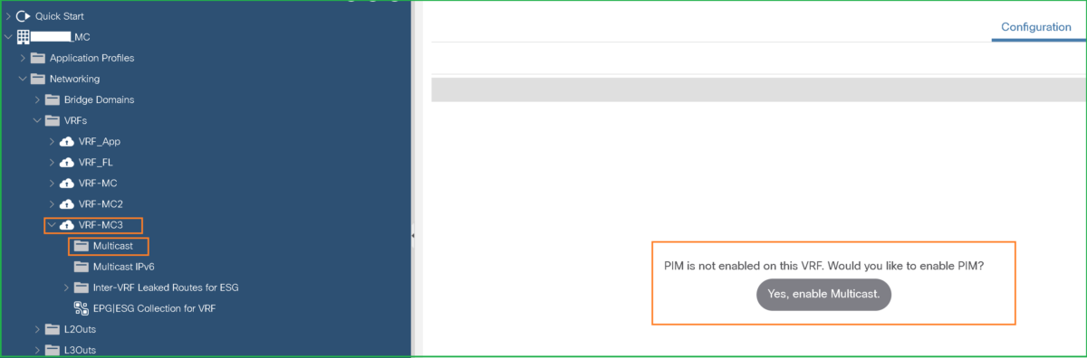
Step-1: Enable Multicast under the VRF
Navigate to Tenant > Networking > VRF > Expand the VRF and select Multicast, then you will see a button “Yes, enable Multicast”:
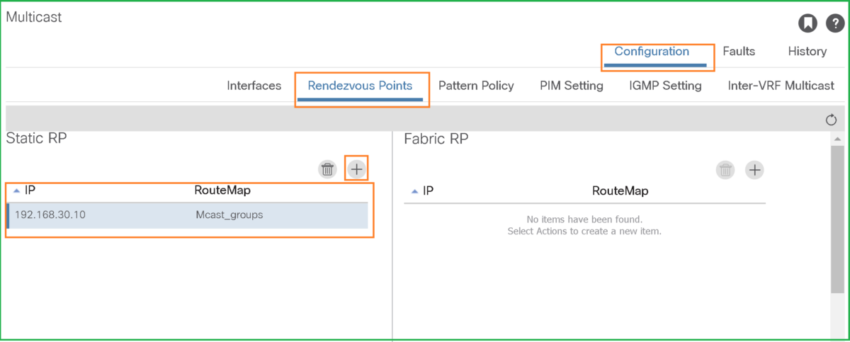
Step-2: Configure the RP
In our example, we will use an External RP, Under Configuration > Rendezvous Points tab, add a static RP IP and specify the Route-map for it:
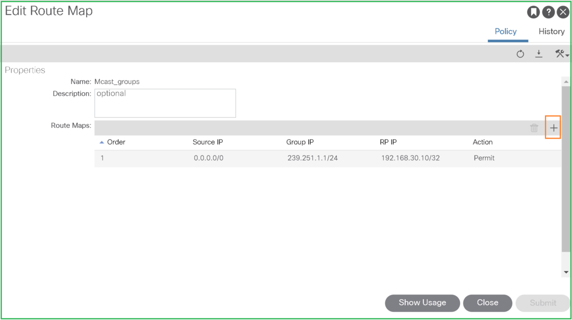
When adding RP IP, create a route-map where you can specify the Source and Multicast group range and its corresponding Rendezvous Point, 0.0.0.0/0 can serve as any source:
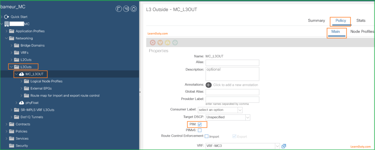
Step-3: Enable PIM under the L3OUT
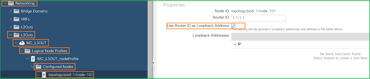
Step-4: Make sure Loopback is Enabled under the multicast BLs
- L3Outs on border leaf should be configured with loopback addresses enabled in the Node profile. A loopback is required for multicast routing on the border leaf.
“Each multicast-enabled VRF requires one or more border leaf switches configured with a loopback interface. You must configure a unique IPv4 loopback address on all nodes in a PIM-enabled L3Out. The Router-ID loopback or another unique loopback address can be used.”
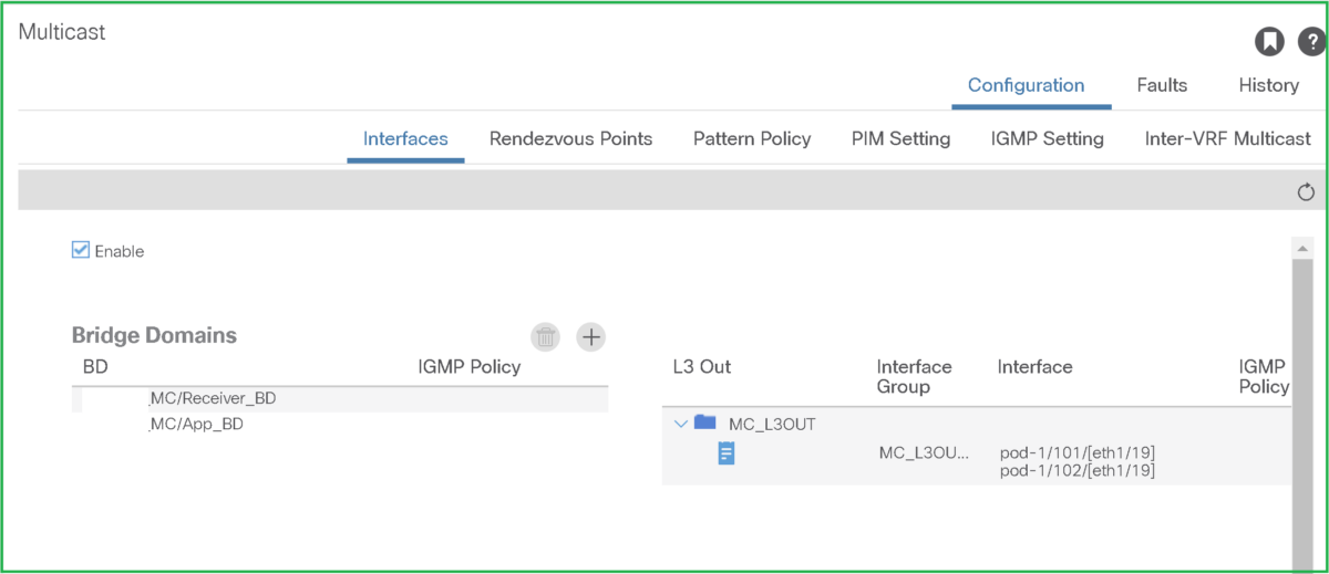
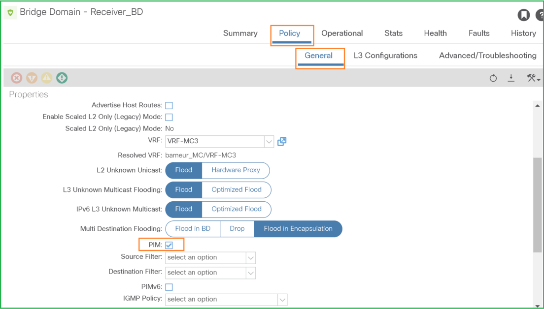
Step-5: Enable PIM under The Bridge Domains
- Enable PIM under The Bridge Domains where you have sources or receivers:
Finally, You can verify these basic configuration from the VRF section: