
VRF (Virtual Routing and Forwarding) & VRF Lite [explained]
![VRF (Virtual Routing and Forwarding) & VRF Lite [explained]](https://learnduty.com/wp-content/uploads/2022/01/image-14.png?v=1647900253)
VRF Concept:
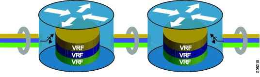
Virtual Routing and Forwarding (VRF) is a technology that allows multiple instances of a routing table to co-exist within the same router at the same time.
One or more logical or physical interfaces may have a VRF and these VRFs do not share routes therefore the packets are only forwarded between interfaces on the same VRF.
VRFs are the TCP/IP layer 3 equivalent of a VLAN. Because the routing instances are independent, the same or overlapping IP addresses can be used without conflicting with each other. Network functionality is improved because network paths can be segmented without requiring multiple routers.
Virtual Route Forward (VRF) is a technique that creates multiple virtual networks within a single network entity. In a single network component, multiple VRF resources create isolation between virtual networks:
VRF Lite
VRF-lite is a feature that enables a service provider to support two or more VPNs, where IP addresses can be overlapped among the VPNs. VRF-lite uses input interfaces to distinguish routes for different VPNs and forms virtual packet-forwarding tables by associating one or more Layer 3 interfaces with each VRF. Interfaces in a VRF can be either physical, such as Ethernet ports, or logical, such as VLAN SVIs, but a Layer 3 interface cannot belong to more than one VRF at any time.
VRF-lite Components:
•![]() Customer edge (CE) devices provide customer access to the service provider network over a data link to one or more provider edge routers. The CE device advertises the site’s local routes to the provider edge router and learns the remote VPN routes from it. A Catalyst 4500 switch can be a CE.
Customer edge (CE) devices provide customer access to the service provider network over a data link to one or more provider edge routers. The CE device advertises the site’s local routes to the provider edge router and learns the remote VPN routes from it. A Catalyst 4500 switch can be a CE.
•![]() Provider edge (PE) routers exchange routing information with CE devices by using static routing or a routing protocol such as BGP, RIPv1, or RIPv2.
Provider edge (PE) routers exchange routing information with CE devices by using static routing or a routing protocol such as BGP, RIPv1, or RIPv2.
The PE is only required to maintain VPN routes for those VPNs to which it is directly attached, eliminating the need for the PE to maintain all of the service provider VPN routes. Each PE router maintains a VRF for each of its directly connected sites. Multiple interfaces on a PE router can be associated with a single VRF if all of these sites participate in the same VPN. Each VPN is mapped to a specified VRF. After learning local VPN routes from CEs, a PE router exchanges VPN routing information with other PE routers by using internal BGP (IBPG).
•![]() Provider routers (or core routers) are any routers in the service provider network that do not attach to CE devices.
Provider routers (or core routers) are any routers in the service provider network that do not attach to CE devices.
With VRF-lite, multiple customers can share one CE, and only one physical link is used between the CE and the PE. The shared CE maintains separate VRF tables for each customer and switches or routes packets for each customer based on its own routing table. VRF-lite extends limited PE functionality to a CE device, giving it the ability to maintain separate VRF tables to extend the privacy and security of a VPN to the branch office.
This figure illustrates the packet-forwarding process in a VRF-lite CE-enabled network.
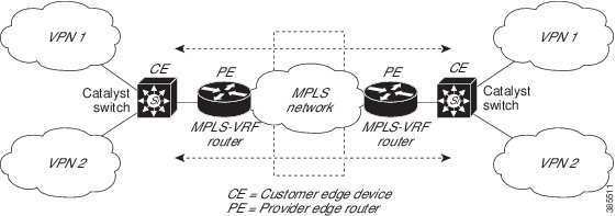
- When the CE receives a packet from a VPN, it looks up the routing table based on the input interface. When a route is found, the CE forwards the packet to the PE.
- When the ingress PE receives a packet from the CE, it performs a VRF lookup. When a route is found, the router adds a corresponding MPLS label to the packet and sends it to the MPLS network.
- When an egress PE receives a packet from the network, it strips the label and uses the label to identify the correct VPN routing table. The egress PE then performs the normal route lookup. When a route is found, it forwards the packet to the correct adjacency.
- When a CE receives a packet from an egress PE, it uses the input interface to look up the correct VPN routing table. If a route is found, the CE forwards the packet within the VPN.
VRF Lite configuration:
Device> enable
Device# configure terminal
Device(config)# vrf definition cisco
Device(config-vrf)# rd 100:1
Device(config-vrf)# exit

Device(config)# interface Loopback0
Device(config-if)# vrf forwarding cisco
Device(config-if)# ip address 10.0.0.2 255.0.0.0
Device(config-if)# exit
References:
https://www.cisco.com/c/en/us/td/docs/voice_ip_comm/cucme/vrf/design/guide/vrfDesignGuide.html
https://en.wikipedia.org/wiki/Virtual_routing_and_forwarding
![OSPF DR and BDR Election Explained [with Configuration]](https://learnduty.com/wp-content/uploads/2022/03/image-33.png?v=1647900046)
![OSPF Neighbor Adjacency Requirements [With Configuration]](https://learnduty.com/wp-content/uploads/2022/03/image-23-418x450.png?v=1647900064)
![OSPF Neighbor States Explained [Step by Step]](https://learnduty.com/wp-content/uploads/2022/03/image-13.png?v=1647900076)
![OSPF Area Types Explained and Configuration [Demystified]](https://learnduty.com/wp-content/uploads/2022/03/image-8.png?v=1647900083)