
OTV Basics Explained & Configuration
Contents
I- OTV Concept:
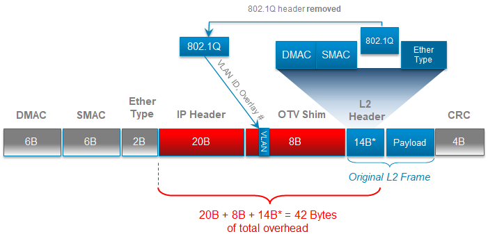
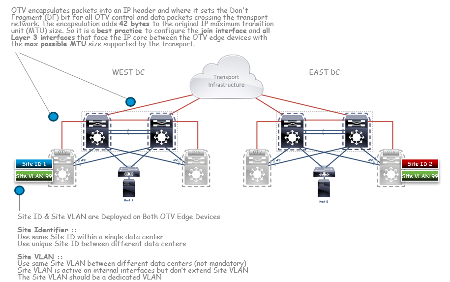
OTV Encapsulation: MAC in IP
•42 Bytes overhead to the packet IP MTU size
(Outer IP Header + OTV Shim) – (Original L2 Header without the 802.1Q header)
•802.1Q header is removed and the VLAN field copied over to the OTV shim header
•Outer OTV shim header contains VLAN, overlay ID number, and an external IP header
•Consider Jumbo MTU Sizing along the path between the source and destination endpoints to account for the extra 42 bytes.
Reference: OTV presentation by “Mark Stinnette, CCIE Data Center #39151″
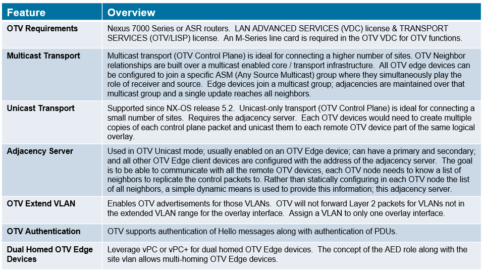
II- Terminology and components
OTV Interfaces type:
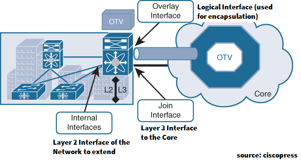
- Internal interfaces: These are the L2 interfaces (usually 802.1q trunks) of the ED that face the site.
- Internal interfaces are regular access or trunk ports.
- Trunk configuration will extend more than one VLAN across the overlay. There is no need to apply OTV-specific configuration to these interfaces.
- Typical Layer 2 functions (like local switching, spanning tree operation, data-plane learning, and flooding) are performed on the internal interfaces.
- Join interface: This is the L3 interface of the ED that faces the core. The join interface is used by the edge device for different purposes:
- “Join” the overlay network and discover the other remote OTV edge devices.
- Form OTV adjacencies with the other OTV edge devices belonging to the same VPN.
- Send/receive MAC reachability information.
- Send/receive unicast and multicast traffic.
- Overlay interface: This is a logical multiaccess multicast-capable interface. It encapsulates Layer 2 frames in IP unicast or multicast headers.
OTV Terminology:

Every time the OTV edge device receives a Layer 2 frame destined for a remote data center site, the frame is logically forwarded to the overlay interface. This instructs the edge device to perform the dynamic OTV encapsulation on the Layer 2 packet and send it to the join interface toward the routed domain.
III- OTV Packet Flow
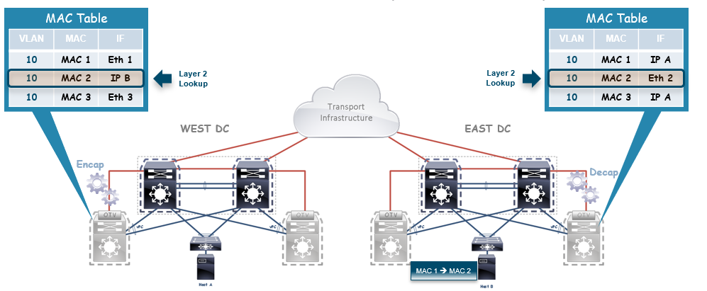
Packet flow Steps:
Step 1 :: The Layer 2 frame is received at the aggregation layer or OTV Edge Device. A traditional Layer 2 lookup is performed, the MAC for Host B’s information in the MAC table does not point to a local Ethernet interface (as you would see in intra-site communication); but to the IP address of the remote OTV Edge Device that advertised that MAC’s reachability information.
Step 2 :: The OTV Edge Device encapsulates the original Layer 2 Frame; with is the source IP of the outer header of the local Join interface & the destination IP which is the IP address of the remote Edge Device Join interface.
Step 3 :: The OTV encapsulated frame (a regular unicast IP packet) is carried across the transport infrastructure and delivered to the remote OTV Edge Device.
Step 4 :: The remote OTV Edge Device decapsulates the frame exposing the original Layer 2 packet.
Step 5 :: The OTV Edge Device performs another Layer 2 lookup on the original Ethernet frame and discovers that it is reachable through a physical interface, which means it is a MAC address local to the site.
Step 6 :: The frame is then delivered to the MAC destination of Host B
IV- OTV Basic configuration

Configuration Example:
1- Unicast Only mode:
Two pieces of configuration are required to deploy OTV across a unicast-only transport infrastructure: first, it is required to define the role of Adjacency Server; whereas the other piece of configuration is required in each OTV edge device not acting as an Adjacency Server (i.e acting as a client).
All client OTV edge devices are configured with the address of the Adjacency Server. All other adjacency addresses are discovered dynamically. Thereby, when a new site is added, only the OTV edge devices for the new site need to be configured with the Adjacency Server addresses. No other sites need additional configuration.
The recommendation is usually to deploy a redundant pair of Adjacency Servers in separate DC sites.
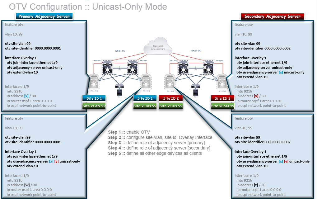
The configuration on the Primary Adjacency Server is very simple and limited to enable AS functionality (otv adjacency-server command). The same command is also required on the Secondary Adjacency Server device, but also needs to point to the Primary AS (leveraging the otv use-adjacency-server command).
Finally, the generic OTV Edge Device must be configured to use both the Primary and Secondary Adjacency Servers. The sequence of adjacency server address in the configuration determine primary or secondary adjacency server role. This order is relevant since an OTV edge device will always use the OTV neighbor-list (oNL) provided by the Primary Adjacency Server, unless it detects that specific device is not available anymore (control plane Hellos are always exchanged as keepalives between each OTV device and the Adjacency Servers).
2-Multicast Mode:
I- Configure OTV Parametres on OTV AND AGG VDC:
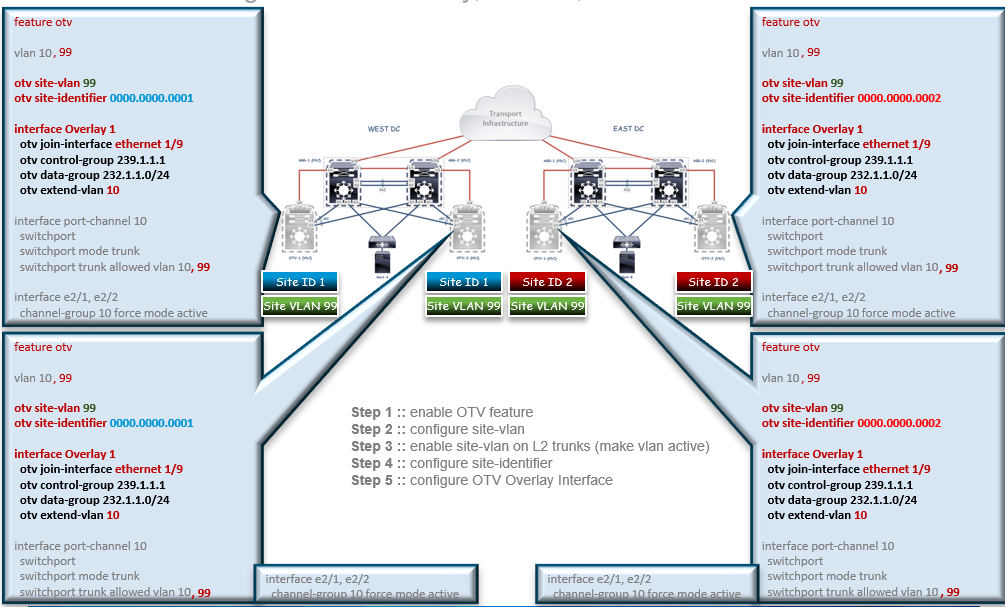
- OTV Control-Group: Create an adjacency relationship with the other Edge Device in order to communicate with it in Multicast (Control Plane)
- OTV Data-Group: Define the Multicast address group used for data exchange between Data Center (Data Plane)
- OTV Extended-VLAN: Define the VLANs that will be allowed to cross the OTV network.
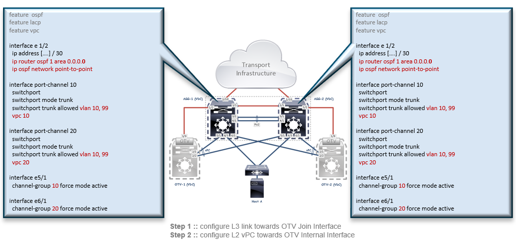
II- Configure Join-Interface and Internal interface & Routing:
- On OTV VDC:

- On AGG VDC:
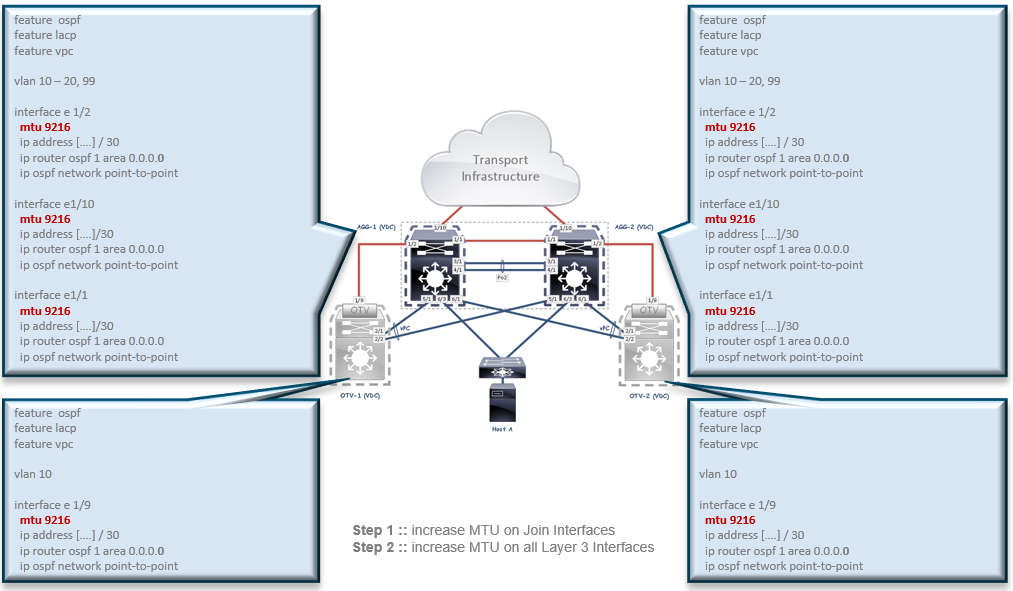
III- Enable Jumbo Frame on Both AGG and OTV VDC:
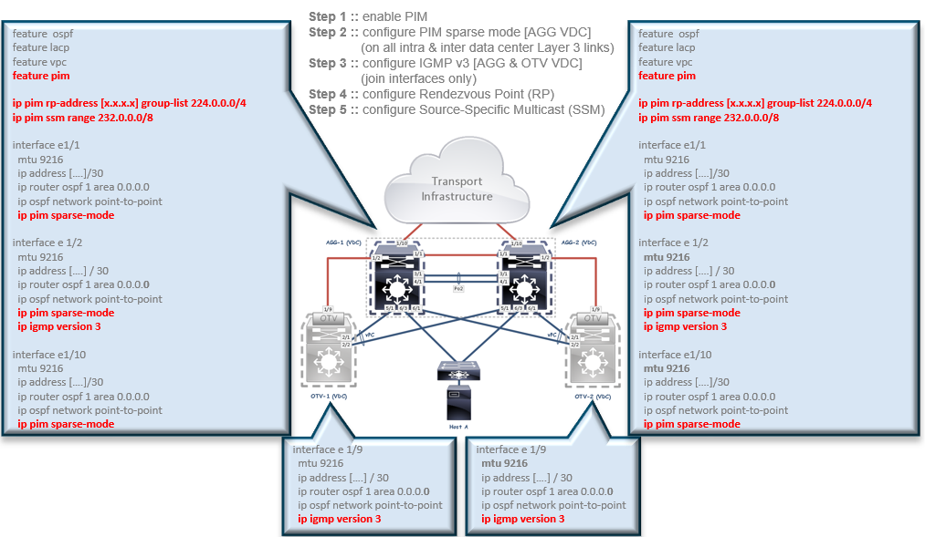
IV- Configure Multicast:
Reference:
https://www.ciscopress.com/articles/article.asp?p=2999385&seqNum=2
Reformed from this prez: OTV presentation by “Mark Stinnette, CCIE Data Center #39151”
![OSPF DR and BDR Election Explained [with Configuration]](https://learnduty.com/wp-content/uploads/2022/03/image-33.png?v=1647900046)
![OSPF Neighbor Adjacency Requirements [With Configuration]](https://learnduty.com/wp-content/uploads/2022/03/image-23-418x450.png?v=1647900064)
![OSPF Neighbor States Explained [Step by Step]](https://learnduty.com/wp-content/uploads/2022/03/image-13.png?v=1647900076)
![OSPF Area Types Explained and Configuration [Demystified]](https://learnduty.com/wp-content/uploads/2022/03/image-8.png?v=1647900083)