
IP Multicast on NX-OS [Explained & Basic configuration]
Contents
PIM Basics on Cisco NX-OS
Cisco NX-OS supports multicasting with Protocol Independent Multicast (PIM) sparse mode. PIM is IP routing protocol-independent and can leverage whichever unicast routing protocols are used to populate the unicast routing table. In PIM sparse mode, multicast traffic is sent only to locations of the network that specifically request it. PIM dense mode is not supported by Cisco NX-OS.
In Cisco NX-OS, multicast is enabled only after you enable the PIM feature on each router and then enable PIM sparse mode on each interface that you want to participate in multicast. You can configure PIM for an IPv4 network. In an IPv4 network, if you have not already enabled IGMP on the router, PIM enables it automatically.
PIM Domains in an IPv4 Network:
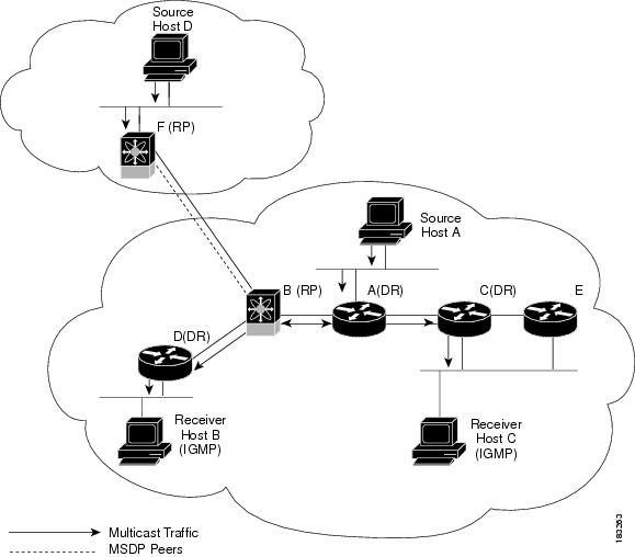
- The lines with arrows show the path of the multicast data through the network. The multicast data originates from the sources at hosts A and D.
- The dashed line connects routers B and F, which are Multicast Source Discovery Protocol (MSDP) peers. MSDP supports the discovery of multicast sources in other PIM domains.
- Hosts B and C receive multicast data by using Internet Group Management Protocol (IGMP) to advertise requests to join a multicast group.
- Routers A, C, and D are designated routers (DRs). When more than one router is connected to a LAN segment, such as C and E, the PIM software chooses one router to be the DR so that only one router is responsible for putting multicast data on the segment.
Router B is the rendezvous point (RP) for one PIM domain, and router F is the RP for the other PIM domain. The RP provides a common point for connecting sources and receivers within a PIM domain.
Cisco NX-OS supports 3 IP Multicast modes:
1- Any-Source Multicast (ASM): provides discovery of multicast sources. It builds a shared tree between sources and receivers of a multicast group and supports switching over to a source tree when a new receiver is added to a group. ASM mode requires that you configure an RP.
Any Source Multicast (ASM) is a PIM tree building mode that uses shared trees to discover new sources and receivers as well as source trees to form shortest paths from receivers to sources:
- The shared tree uses a network node as the root, called the rendezvous point (RP).
- The source tree is rooted at first-hop routers, directly attached to each source that is an active sender.
The ASM mode requires an RP for a group range. An RP can be configured statically or learned dynamically by the Auto-RP or BSR group-to-RP discovery protocols. If an RP is learned, the group operates in ASM mode.
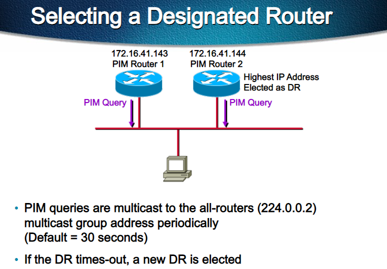
Designated Routers: In PIM ASM mode, the software chooses a designated router (DR) from the routers on each network segment. The DR is responsible for forwarding multicast data for specified groups and sources on that segment:
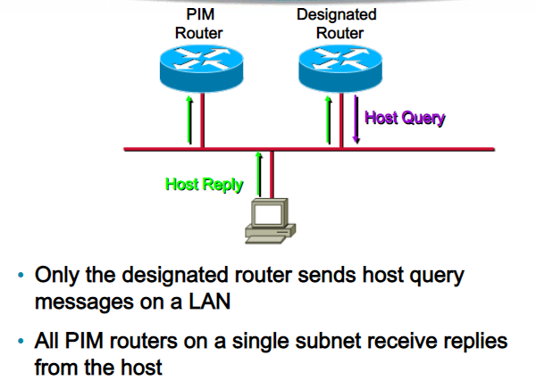
The DR for each LAN segment is determined as described in the Hello messages.
In ASM mode, the DR is responsible for unicasting PIM register packets to the RP. When a DR receives an IGMP membership report from a directly connected receiver, the shortest path is formed to the RP, which may or may not go through the DR. The result is a shared tree that connects all sources transmitting on the same multicast group to all receivers of that group.
The ASM mode is the default mode when you configure RPs.
2- Bidirectional shared trees (Bidir): is a PIM mode that, like the ASM mode, builds a shared tree between receivers and the RP but does not support switching over to a source tree when a new receiver is added to a group.
In the Bidir mode, the router that is connected to a receiver is called the designated forwarder (DF) because multicast data can be forwarded directly from the designated router (DR) to the receiver without first going to the RP. The Bidir mode requires that you configure an RP.
The router with the lowest IP address on the LAN segment is elected as the Designated Forwarder (DF), DF establishes a Loop-Free shared tree rooted at the RP.
The Bidir mode can reduce the amount of resources required on a router when there are many multicast sources and can continue to operate whether or not the RP is operational or connected.
3- Source-Specific Multicast (SSM): is a PIM mode that builds a source tree that originates at the designated router on the LAN segment that receives a request to join a multicast source. Source trees are built by sending PIM join messages in the direction of the source. The SSM mode does not require any RP configuration.
The SSM mode allows receivers to connect to sources outside the PIM domain.
PIM Messages:
Hello Messages:
The PIM process begins when the router establishes PIM neighbor adjacencies by sending PIM hello messages to the multicast IPv4 address 224.0.0.13. Hello messages are sent periodically at the interval of 30 seconds. When all neighbors have replied, the PIM software chooses the router with the highest priority in each LAN segment as the designated router (DR). The DR priority is based on a DR priority value in the PIM hello message. If the DR priority value is not supplied by all routers or the priorities match, the highest IP address is used to elect the DR.
The hello message also contains a hold-time value, which is typically 3.5 times the hello interval. If this hold time expires without a subsequent hello message from its neighbor, the device detects a PIM failure on that link.
Join-Prune Messages:
When the DR receives an IGMP membership report message from a receiver for a new group or source, the DR creates a tree to connect the receiver to the source by sending a PIM join message out the interface toward the rendezvous point (ASM mode). The rendezvous point (RP) is the root of a shared tree, which is used by all sources and hosts in the PIM domain in the ASM mode.
When the DR determines that the last host has left a group or source, it sends a PIM prune message to remove the path from the distribution tree.
PIM Register Messages
PIM register messages are unicast to the RP by designated routers (DRs) that are directly connected to multicast sources. The PIM register message has the following functions:
- To notify the RP that a source is actively sending to a multicast group.
- To deliver multicast packets sent by the source to the RP for delivery down the shared tree.
The DR continues to send PIM register messages to the RP until it receives a Register-Stop message from the RP. The RP sends a Register-Stop message in either of the following cases:
- The RP has no receivers for the multicast group being transmitted.
- The RP has joined the SPT to the source but has not started receiving traffic from the source.
The following example shows how to configure the IP source address of the register message to the loopback 3 interface of a DR:
ip pim register-source loopback 3State Refreshes
PIM requires that multicast entries are refreshed within a 3.5-minute timeout interval. The state refresh ensures that traffic is delivered only to active listeners, and it keeps routers from using unnecessary resources.
To maintain the PIM state, the last-hop DR sends join-prune messages once per minute. State creation applies to both (*, G) and (S, G) states as follows:
- (*, G) state creation example—An IGMP (*, G) report triggers the DR to send a (*, G) PIM join message toward the RP.
- (S, G) state creation example—An IGMP (S, G) report triggers the DR to send an (S, G) PIM join message toward the source.
If the state is not refreshed, the PIM software tears down the distribution tree by removing the forwarding paths in the multicast outgoing interface list of the upstream routers.
Rendezvous Points:
Static RP:
You can statically configure an RP for a multicast group range. You must configure the address of the RP on every router in the domain.
You can define static RPs for the following reasons:
- To configure routers with the Anycast-RP address
- To manually configure an RP on a device
Auto-RP:
Auto-RP is a Cisco protocol that was introduced prior to the Internet standard bootstrap router mechanism. You configure Auto-RP by selecting candidate mapping agents and RPs. Candidate RPs send their supported group range in RP-Announce messages to the Cisco RP-Announce multicast group 224.0.1.39. An Auto-RP mapping agent listens for RP-Announce messages from candidate RPs and forms a Group-to-RP mapping table. The mapping agent multicasts the Group-to-RP mapping table in RP-Discovery messages to the Cisco RP-Discovery multicast group 224.0.1.40.
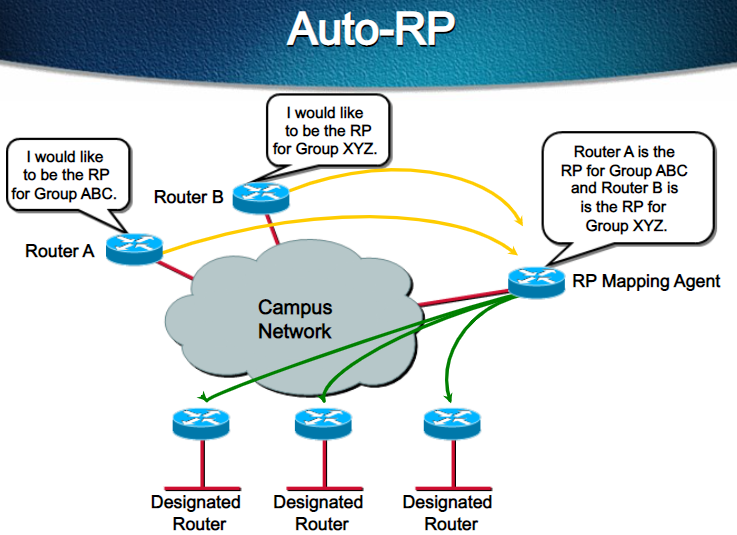
This figure shows the Auto-RP mechanism. Periodically, the RP mapping agent multicasts the RP information that it receives to the Cisco-RP-Discovery group 224.0.1.40 (shown by the solid lines in the figure).
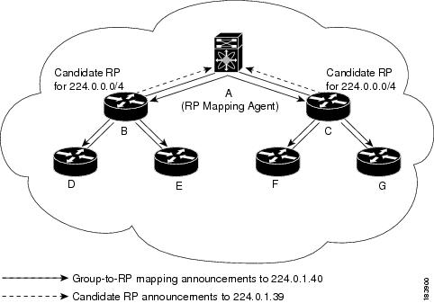
By default, routers are not enabled to listen or forward Auto-RP messages. You must enable the Auto-RP listening and forwarding feature so that the Auto-RP mechanism can dynamically inform routers in the PIM domain of the group-to-RP mapping.
Anycast-RP:
You can use PIM Anycast-RP to assign a group of routers, called the Anycast-RP set, to a single RP address that is configured on multiple routers. The set of routers that you configure as Anycast-RPs is called the Anycast-RP set. This method is the only RP method that supports more than one RP per multicast group, which allows you to load balance across all RPs in the set. The Anycast RP supports all multicast groups.
PIM register messages are sent to the closest RP, and PIM join-prune messages are sent in the direction of the closest RP as determined by the unicast routing protocols. If one of the RPs goes down, unicast routing ensures these messages will be sent in the direction of the next-closest RP.
You must configure PIM on the loopback interface that is used for the PIM Anycast RP and the PIM Bidir RP.
BSRs:
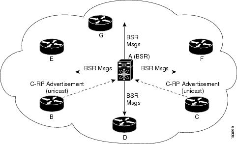
The bootstrap router (BSR) ensures that all routers in the PIM domain have the same RP cache as the BSR. You can configure the BSR to help you select an RP set from BSR candidate RPs. The function of the BSR is to broadcast the RP set to all routers in the domain. You select one or more candidate BSRs to manage the RPs in the domain. Only one candidate BSR is elected as the BSR for the domain.
This figure shows the BSR mechanism. Router A, the software-elected BSR, sends BSR messages out all enabled interfaces (shown by the solid lines in the figure). The messages, which contain the RP set, are flooded hop by hop to all routers in the network. Routers B and C are candidate RPs that send their candidate-RP advertisements directly to the elected BSR (shown by the dashed lines in the figure).
The elected BSR receives candidate-RP messages from all the candidate RPs in the domain. The bootstrap message sent by the BSR includes information about all of the candidate RPs. Each router uses a common algorithm to select the same RP address for a given multicast group.
In the RP selection process, the RP address with the best priority is determined by the software. If the priorities match for two or more RP addresses, the software might use the RP hash in the selection process. Only one RP address is assigned to a group.
By default, routers are not enabled to listen or forward BSR messages. You must enable the BSR listening and forwarding feature so that the BSR mechanism can dynamically inform all routers in the PIM domain of the RP set assigned to multicast group ranges.
The following guidelines and limitations apply to Rendezvous Points (RP):
- Configure candidate RP intervals to a minimum of 15 seconds.
- Do not configure both Auto-RP and BSR protocols in the same network.
- PIM6 does not support BSRs and Auto-RP.
- You must configure PIM on the loopback interface that is used for the PIM Anycast RP and the PIM Bidir RP.
PIM Configuration on NX-OS:
I- PIM Sparse Mode:
Step-1: Enabling the PIM Feature:
switch(config)# feature pimCode language: PHP (php)Step-2: Enable PIM-SM on an interface:
Switch(config)# interface ethernet 1/8
Switch(config-if-range)# ip pim sparse-modeCode language: PHP (php)
Step-3: Configure RP address:
- Static RP address:
Switch(config)# ip pim rp-address 10.1.1.1 group-list 224.0.0.0/9Code language: PHP (php)To manually select an RP, you need to configure it on every participating router.
- Implement Auto-RP:
To implement Auto-RP, you need to configure one or more RP candidates and one or more mapping agents.
- Configures an Auto-RP mapping agent. The source IP address used in Auto-RP Discovery messages is the IP address of the interface.
SwitchRP(config)# ip pim auto-rp rp-candidate ethernet 2/1 group-list 239.0.0.0/24Code language: PHP (php)- Configures an Auto-RP candidate RP. The default scope is 32. The default interval is 60 seconds. By default, the command creates an ASM candidate RP. Use the bidir option to create a Bidir candidate RP.
SwitchMA(config)# ip pim auto-rp mapping-agent ethernet 2/1Code language: PHP (php)- implement BSR:
Configures a candidate bootstrap router (BSR). The source IP address used in a bootstrap message is the IP address of the interface. The hash length ranges from 0 to 32 and has a default of 30.
SwitchRP(config)# ip pim rp-candidate ethernet 2/1 group-list 239.0.0.0/24Code language: PHP (php)Priority assigned to this BSR. The software elects the BSR with the highest priority, or if the BSR priorities match, the software elects the BSR with the highest IP address. This value ranges from 0, the lowest priority, to 255 and has a default of 64.
SwitchBSR(config)# ip pim bsr-candidate ethernet 2/1 hash-len 24 priority 192Code language: PHP (php)- Anycast RP:
1- Configure the RP address that you configure on all routers in the Anycast-RP set.
switch# <kbd><strong>configure terminal</strong></kbd>
switch(config)# <kbd><strong>interface loopback 0</strong></kbd>
switch(config-if)# <kbd><strong>ip address 192.0.2.3/32</strong></kbd>
switch(config-if)# <kbd><strong>ip pim sparse-mode</strong></kbd>Code language: HTML, XML (xml)
2- Configure a loopback with an address to use in communication between routers in the Anycast-RP set for each router that you want to be in the Anycast-RP set.
switch# <kbd><strong>configure terminal</strong></kbd>
switch(config)# <kbd><strong>interface loopback 1</strong></kbd>
switch(config-if)# <kbd><strong>ip address 192.0.2.31/32</strong></kbd>
switch(config-if)# <kbd><strong>ip pim sparse-mod</strong></kbd>eCode language: HTML, XML (xml)
3- Configure the Anycast-RP parameters and repeat with the IP address of each Anycast-RP for each router that you want to be in the Anycast-RP set. This example shows two Anycast-RPs.
switch# <kbd><strong>configure terminal</strong></kbd>
switch(config)# <kbd><strong>ip pim anycast-rp 192.0.2.3 193.0.2.31</strong></kbd>
switch(config)# <kbd><strong>ip pim anycast-rp 192.0.2.3 193.0.2.32</strong></kbd>Code language: HTML, XML (xml)
Note: BIDIR-PIM configuration equals to PIM-SM configuration for all RP distribution modes with the added bidir attribute.
II- PIM SSM:
PIM-SSM configuration requires no RP, but you must enable IGMPv3.
SwitchA(config)# ip pim ssm range 224.0.0.0/4
SwitchA(config-if)# ip igmp version 3Code language: PHP (php)
Note: The Cisco Nexus 9000 Series switches do not support SSM.
Inter-Multicast Domain routing:
PIM is typically used for multicast routing within a single routing domain or AS. To support multicast routing between two separate routing domains, two protocols can be used:
- Multicast Source Discovery Protocol (MSDP): MSDP is used to announce the availability of multicast sources between RPs in the different domains. First-hop routers register sources through PIM with the RP within their domain. MSDP can then be used to advertise that information to RPs in different routing domains.
- Multicast Border Gateway Protocol (MBGP): Multicast routing depends on unicast routing information for RPF, which is used for loop prevention and to build trees toward a source or RP. MBGP exchanges IP prefix information that will be used for multicast RPF between two autonomous systems.
Reference:
https://www.cisco.com/c/en/us/td/docs/dcn/nx-os/nexus9000/101x/configuration/multicast-routing/cisco-nexus-9000-series-nx-os-multicast-routing-configuration-guide-release-101x/m-overview.html
https://www.cisco.com/c/en/us/td/docs/switches/datacenter/nexus9000/sw/6-x/multicast/configuration/guide/b_Cisco_Nexus_9000_Series_NX-OS_Multicast_Routing_Configuration_Guide/b_Cisco_Nexus_9000_Series_NX-OS_Multicast_Routing_Configuration_Guide_chapter_011.html#concept_ACB8FB91DF6D4CF0925449266409AF8F
![OSPF DR and BDR Election Explained [with Configuration]](https://learnduty.com/wp-content/uploads/2022/03/image-33.png?v=1647900046)
![OSPF Neighbor Adjacency Requirements [With Configuration]](https://learnduty.com/wp-content/uploads/2022/03/image-23-418x450.png?v=1647900064)
![OSPF Neighbor States Explained [Step by Step]](https://learnduty.com/wp-content/uploads/2022/03/image-13.png?v=1647900076)
![OSPF Area Types Explained and Configuration [Demystified]](https://learnduty.com/wp-content/uploads/2022/03/image-8.png?v=1647900083)